Hardware
HardwareHardware
Welcome to the hardware review section of the site. Here I have some reviews of hardware that I've used personally. Mostly, it will be hardware I really like because I don't have time to write about the stuff I don't like. (Unless I really, really hate it and wouldn't wish it on my worst enemy.)
Antec Three Hundred Gaming Case
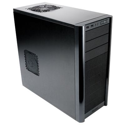
Antec Three Hundred Gaming CaseI recently upgraded my son's gaming PC to dual Nvidia 8800 GTs in SLI and immediately noticed the temperatures were much higher than they should be. This was a very old Antec case and lacked sufficient airflow. I couldn't find a model number on it anywhere, but its QC stamp was from 2000. It only had two fans (other than the fan in the PSU): an 80mm fan sucking in air at the bottom front and a 60mm fan in the top back, just below the power supply. Time for a new case to handle the heat generation of dual GPUs and the CPU. Since I really love my Antec Nine Hundred case, but I didn't need quite the same room for this build, I decided to try its little brother the Antec Three Hundred. (The link is to the newer Antec Three Hundred Two, which is the replacement.)
Cheap, But Not Cheap
The Antec Three Hundred sells at Newegg.com from $45 to $70 depending on your luck plus shipping. Antec later introduced the Antec Three Hundred Illusion case which goes for about $70 that includes two Antec 120mm three speed fans in the front drive bays. The latter case a great deal since there are no quality 120mm fans for difference in cost.
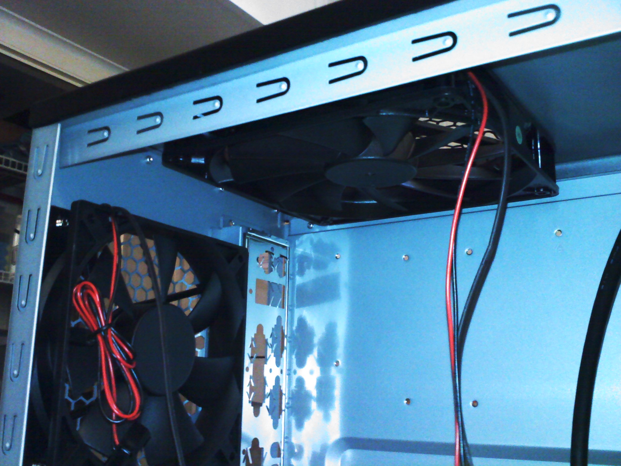
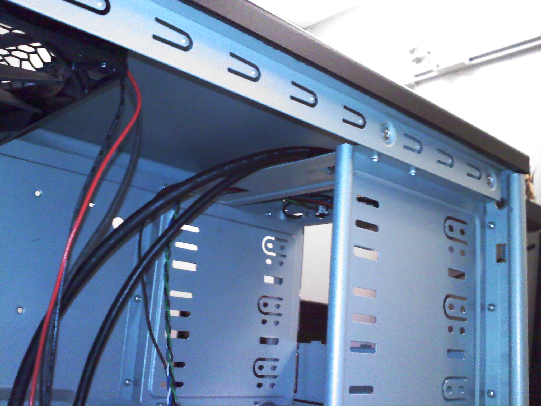
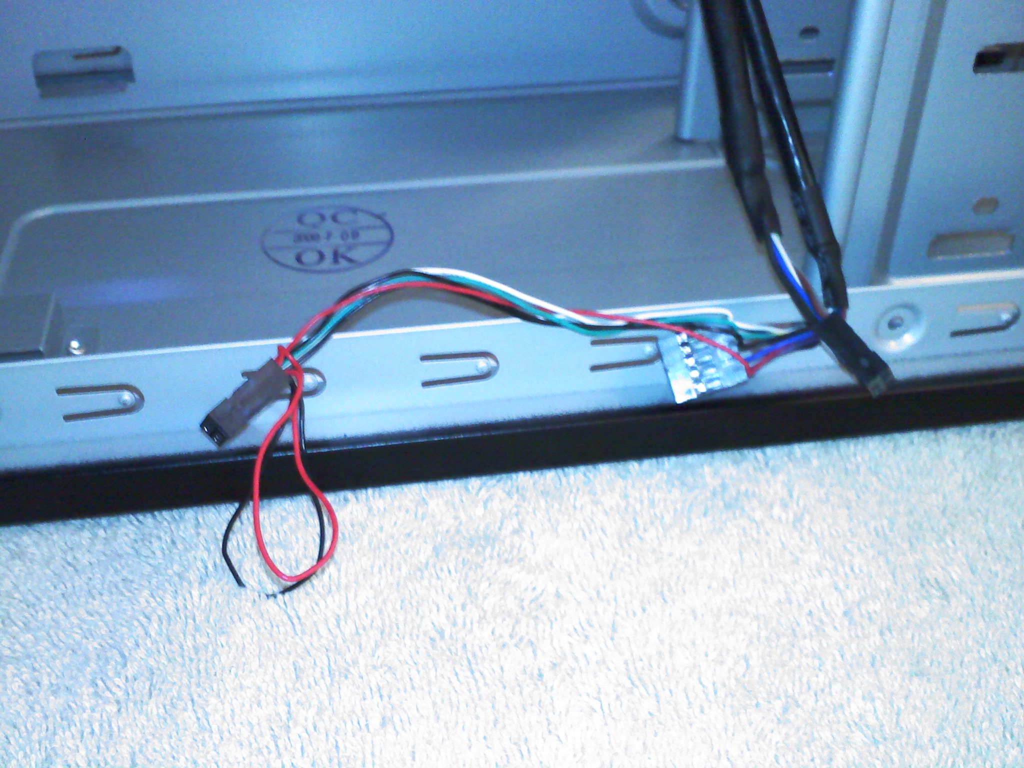
Either way, that's a very good price for a very solid case. I'll point out the little extras that make this case a bit more of an extra value. I'll also point out a few things I would have like to have seen. Let's get right into it (literally), shall we? Peeking into an empty case can only reveal so much, but it's nice to note how much room this case has for a mid-tower case. The first picture below (click on the thumbnail to expand the picture) shows that the case has nine 5 1/4" drive bays. Only three of those are truly externally accessible (unlike the Antec Nine Hundred where there are nine externally accessible drive bays). That said, very few people would ever need more than three - many only needing one. The second picture shows the included 140mm top and 120mm rear Antec Tri-Cool (i.e., three speed) fans, which are in the perfect spot to draw the air directly from the CPU on most motherboards. This is probably equivalent to upgrading your CPU heatsink/fan combo without spending anything extra. The last couple pictures show the external drive bays from the inside (along with the front panel wiring) and the front panel audio cable which has both AC97 and HD audio connectors.

Moving to the front of the case, there are two fan mounts that are removed by loosening a pair of thumb screws in each mount. The first picture below shows the upper fan mount removed. The front panel is pretty standard fare in that it has two USB ports, headphone and microphone jacks, a reset switch, a power switch, and LEDs for power and hard drive activity. I wish they'd also considered adding an ESATA port, but perhaps I'm the only person finding those almost required any more. None of the slots in the drive bay in the bottom allow for a floppy drive. One could put in one of the top external bays with a 5.25" to 3.5" adapter that Antec lists as an optional part, which includes a floppy slot. For most builds with late model motherboards, there's really no need for a floppy drive, so this isn't much of a problem

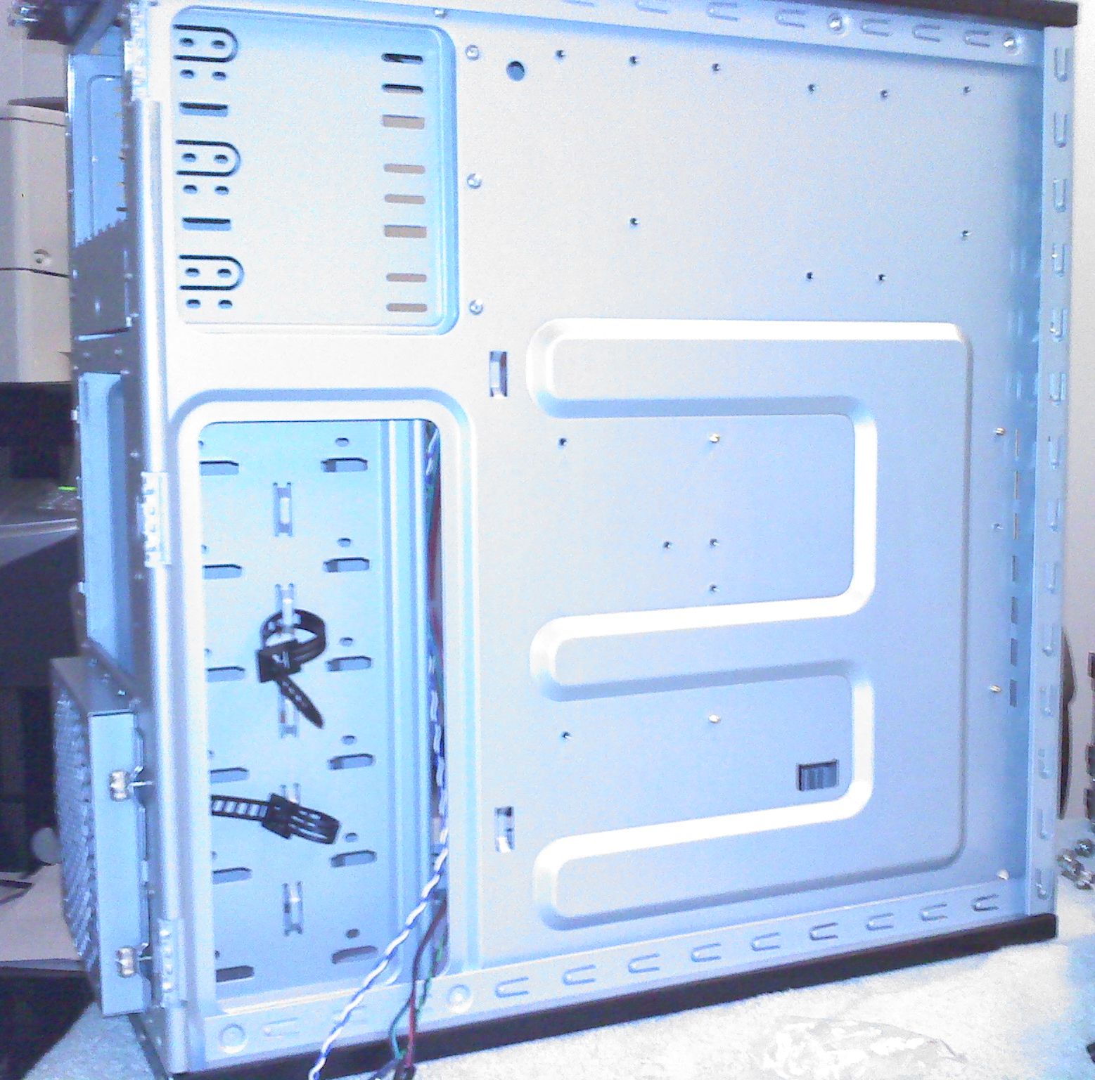
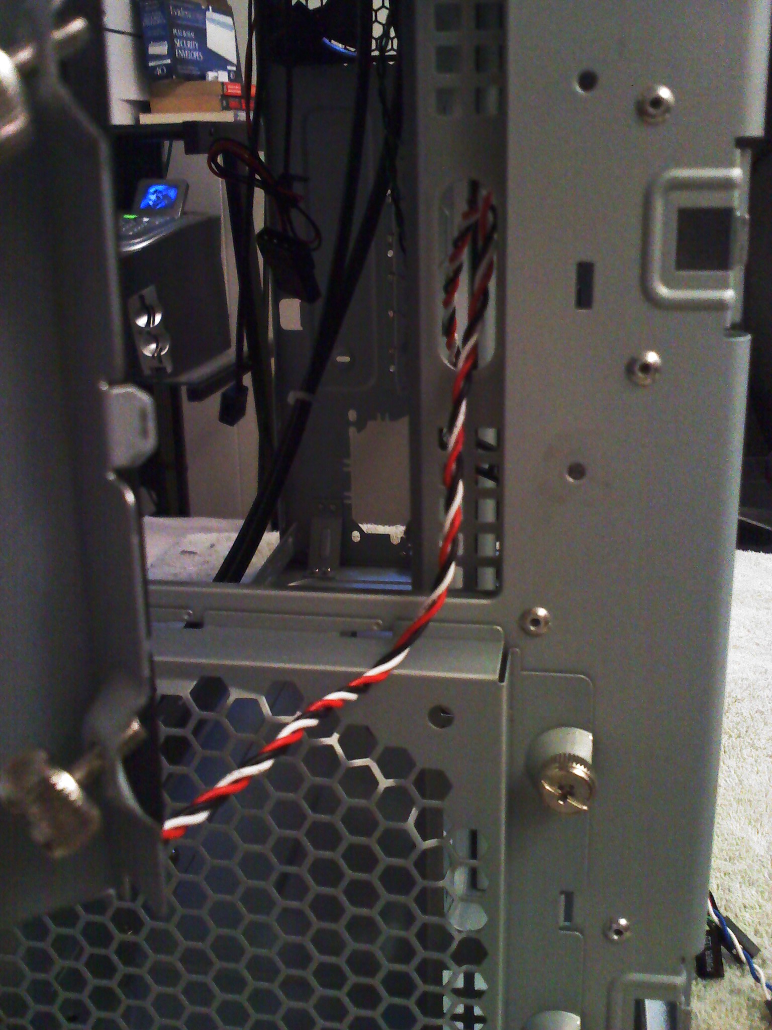
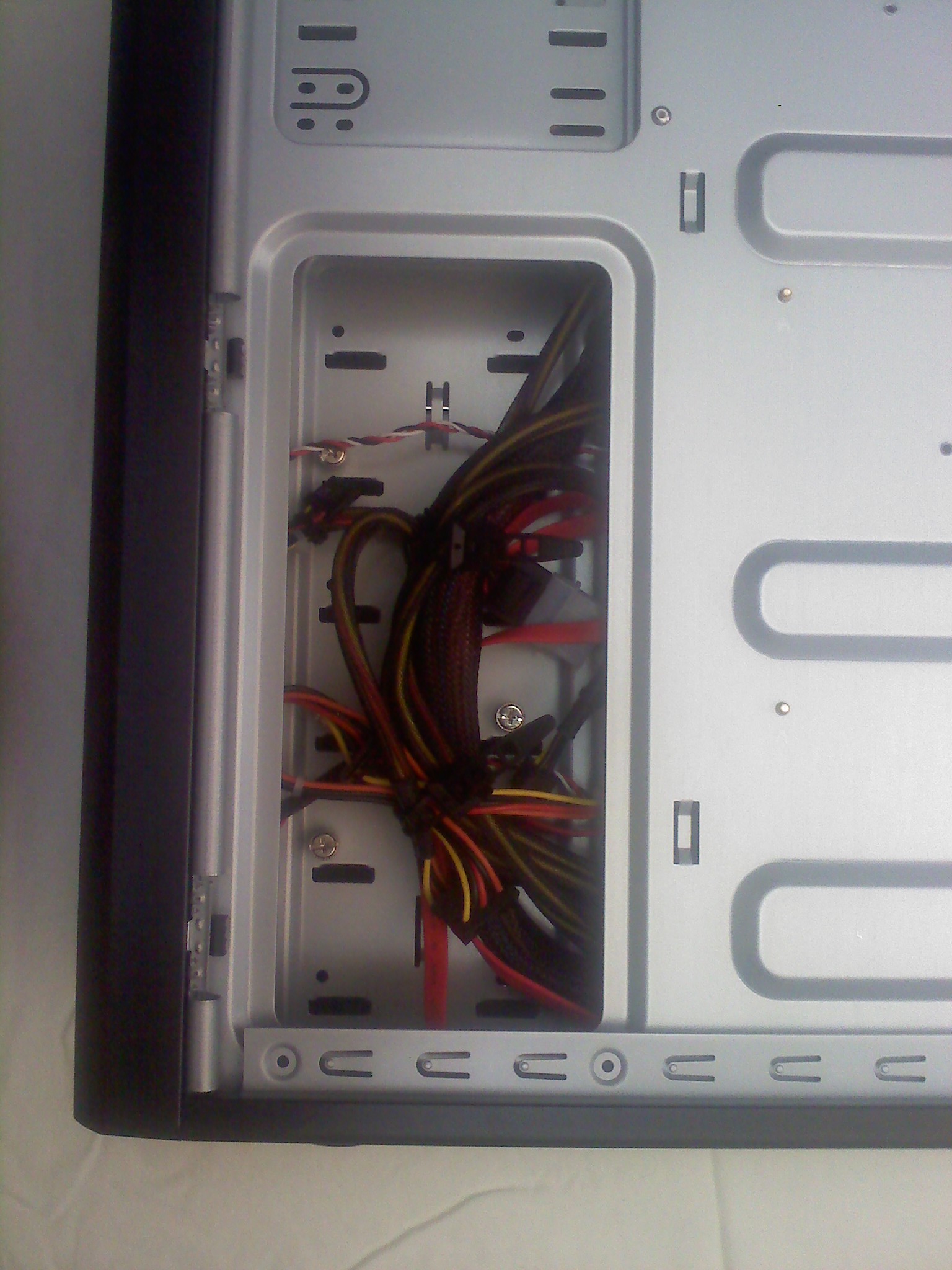
A look at the right side of the case shows that there is some hidden cable management there with a couple of straps included. One thing I would have liked to see and which I have started seeing in high-end cases, is a cut out under the motherboard where the CPU would likely sit. This allows a heavy duty CPU cooler that includes a bottom plate to be installed or removed without taking the motherboard out of the case. I wouldn't take any points away for the lack of said cut out - if I were giving points - but it would have been nice. Most people never tinker with their motherboards once installed. I do. I also wish the case included some form of a PC speaker (or that motherboard manufacturers would put a piezoelectric speaker on the motherboard itself). I'm old-fashioned in that I like hearing that POST beep upon powering up the PC.
The Build Begins
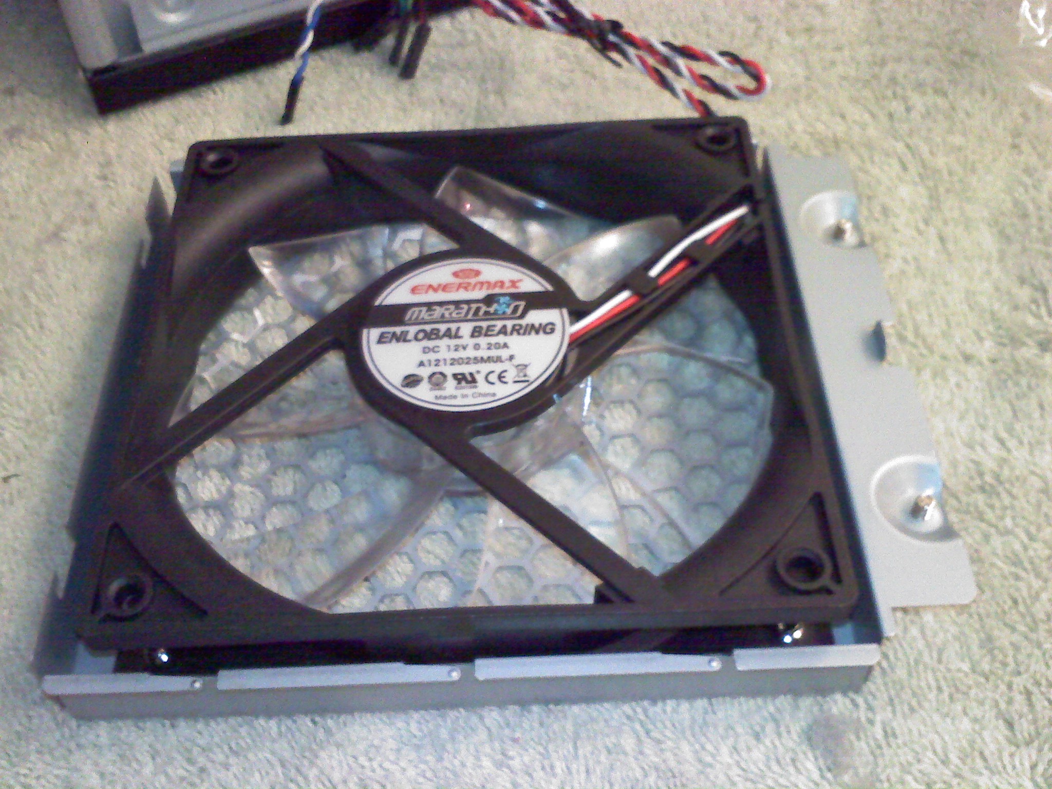
The Antec Three Hundred doesn't include the 120mm fans in the drive bays or the one on the side panel, however with three disk drives and dual graphics cards, those are all desirable. (See also, the Antec Three Hundred Illusion case mentioned above that seems to include two of the three fans for only $10 more.) For this build, I used three Enermax UC-12EB fans. I use these in the 120mm and 80mm sizes a lot. The reasons are that they are cheap (from Newegg.com anyway), utterly quiet, move lots of air and last forever (where "forever" means that at least for the two years that I've been using them, none have failed). The ENLOBAL Magnetic Barometric Bearing probably has a lot to do with their reliability. The 120mm version produces less than 17db sound while moving 44 CFM of air at only 1000 RPM. They don't have fancy lights; they just work efficiently and quietly .. in an Antec case even. (This assumes you know that Antec and Enermax are [two of my favorite] competitors in the case and cooling market).
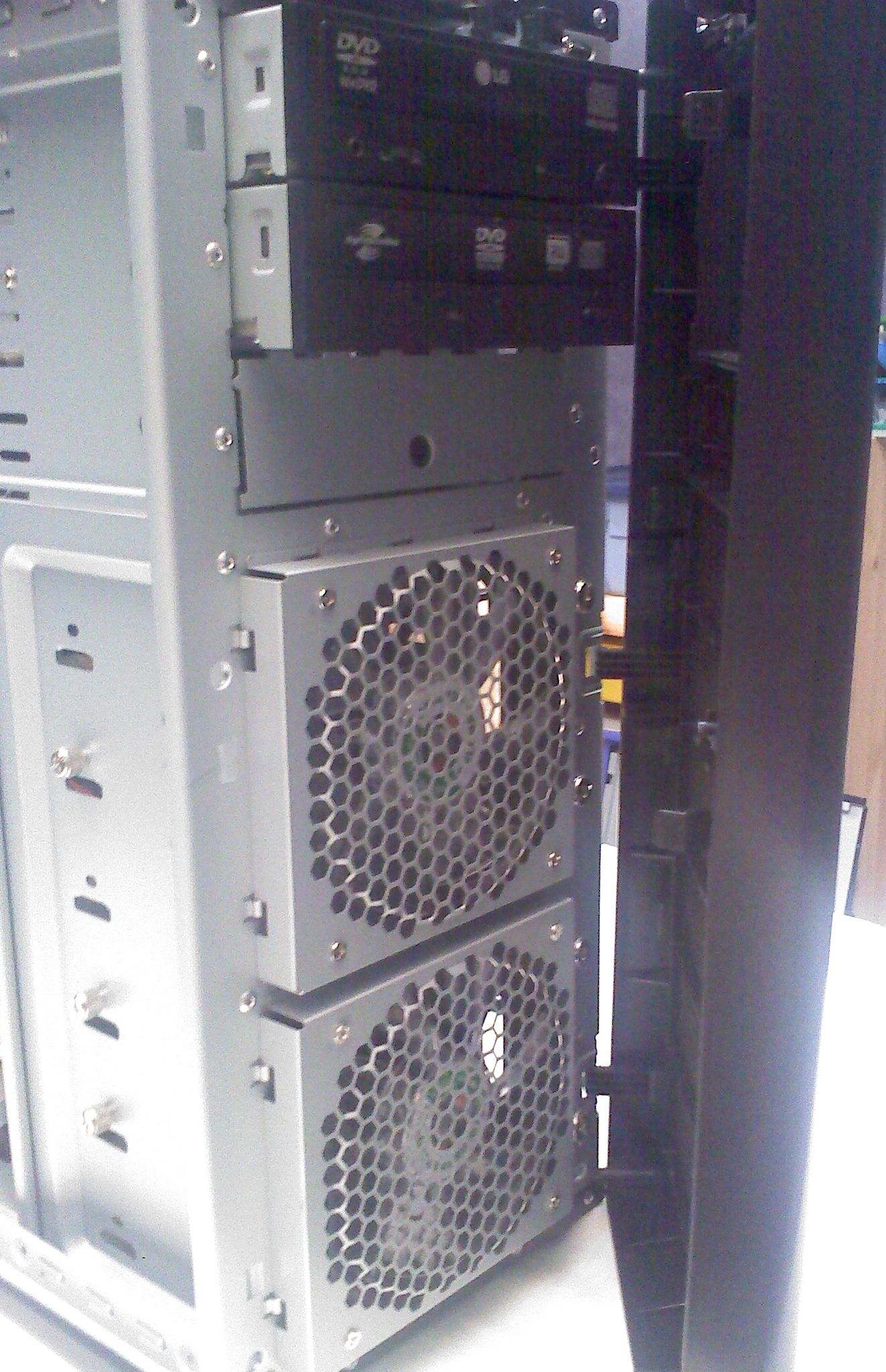
The first picture below shows an Enermax fan installed in the drive bay mount. Next, the drive bay fan mount hooks over a couple slots on the left and is fastened into place using the thumb screws on the right. This makes them extremely quick to install and replace. The case designers included cable management slots behind the fan mounts as shown in the last picture. It's that attention to detail that makes me impressed with this case. When screwed down tightly, the fans are not likely to vibrate. Once the optical drives are installed (two of them in this build), the front panel hooks onto the right and clips tightly into place on the left. That's a very nice clean way to mount the front panel without requiring tools or screws.
Now, it's time to get serious installing the bulk of the hardware. The motherboard went in without consequence, and the picture below shows the three drives in their slots in the bay. They are held in place with thumb screws seen on the very far right of the picture, which are included with the case. Some "cheap" cases also get cheap by including few or no screws. That's not true with the Antec Three Hundred. There are enough screws here for at least the six drive bays, the motherboard (including nine standoffs) and several other assorted screws. This build is still using a couple IDE optical DVD-ROM and DVD-RW drives. As these die, I replace them with SATA drives, but haven't found a reason to do a wholesale replacement on working drives.
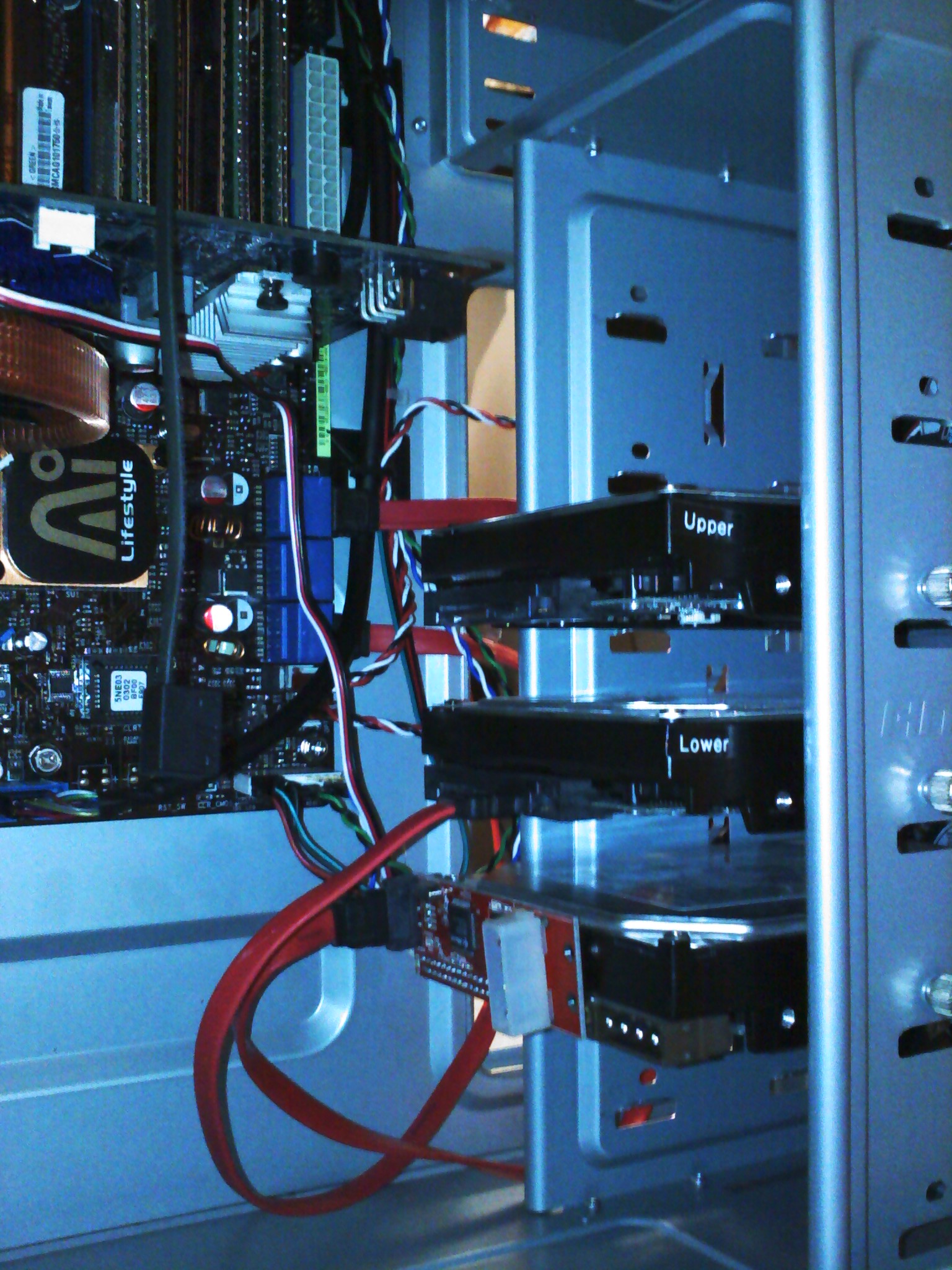
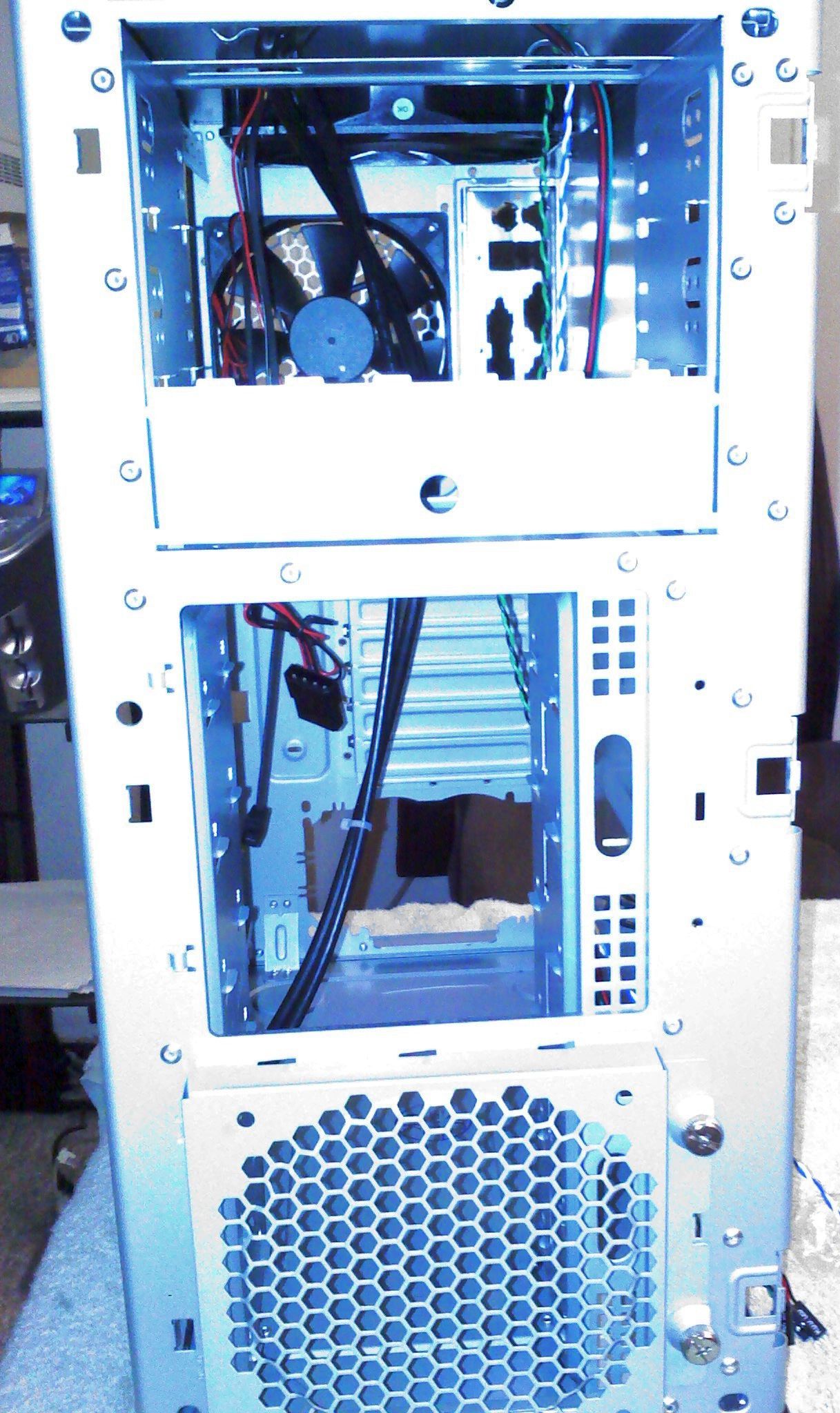
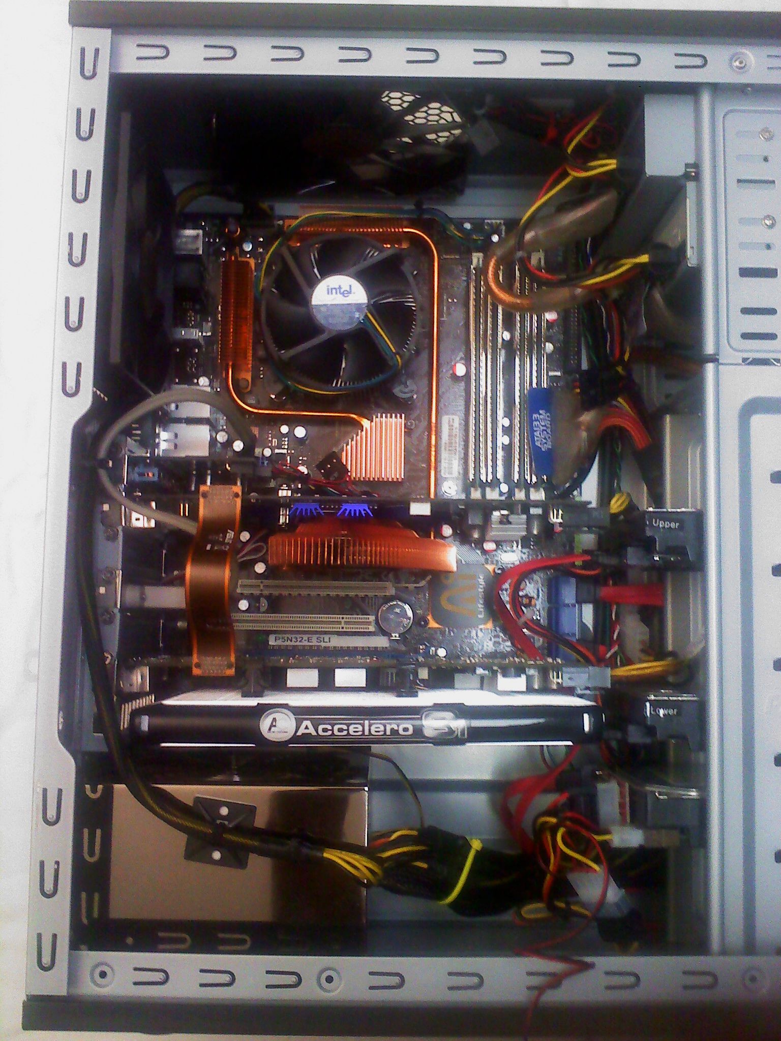
The Antec Three Hundred has a bottom-mounted power supply unit (PSU) and one of the consequences of that is that it brings the motherboard closer to the external optical drives at the top of the case. Looking at the first picture below, the distance between the blue IDE port on right side of the motherboard and the first IDE optical drive is now about three inches. Too bad the shortest dual-device round IDE cable I have is about 12 inches long. The hidden cable management behind the internal drive bays will be used to hide most of it. As the second picture shows, another advantage is that the CPU is indeed very close to the top and rear fans, which will help keep it cool. Having the power supply at the bottom did make it hard to route the 8-pin auxiliary power connector to the motherboard except straight up the back of the case.


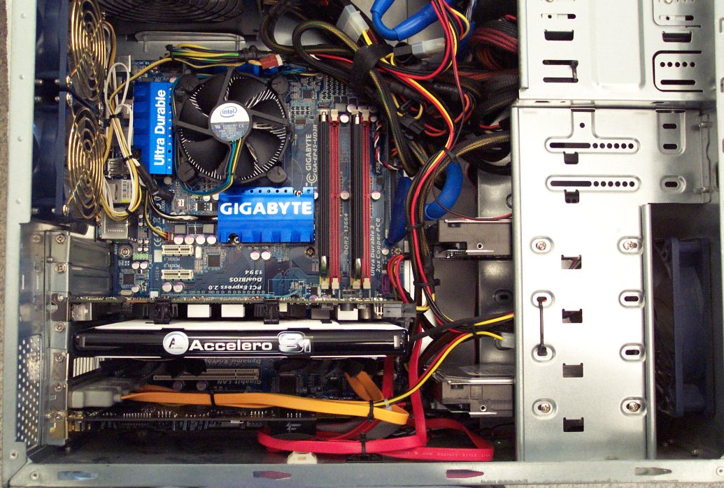
The first picture below is of the finished build. In order to maintain airflow and clearance, I had to move one of the disk drives up one slot in the bay to clear the back of the video card and it's power plug (but luckily there's plenty of drive bay slots). I would recommend getting the measurements of a long video card though to make sure it fits in this case. The 8800 GTs are not the longest cards out there and they are a tight fit. The final picture of this series shows how the cable management took up all the extra slack of the cables. The airflow in this case is pretty decent, but not as good as a larger case.
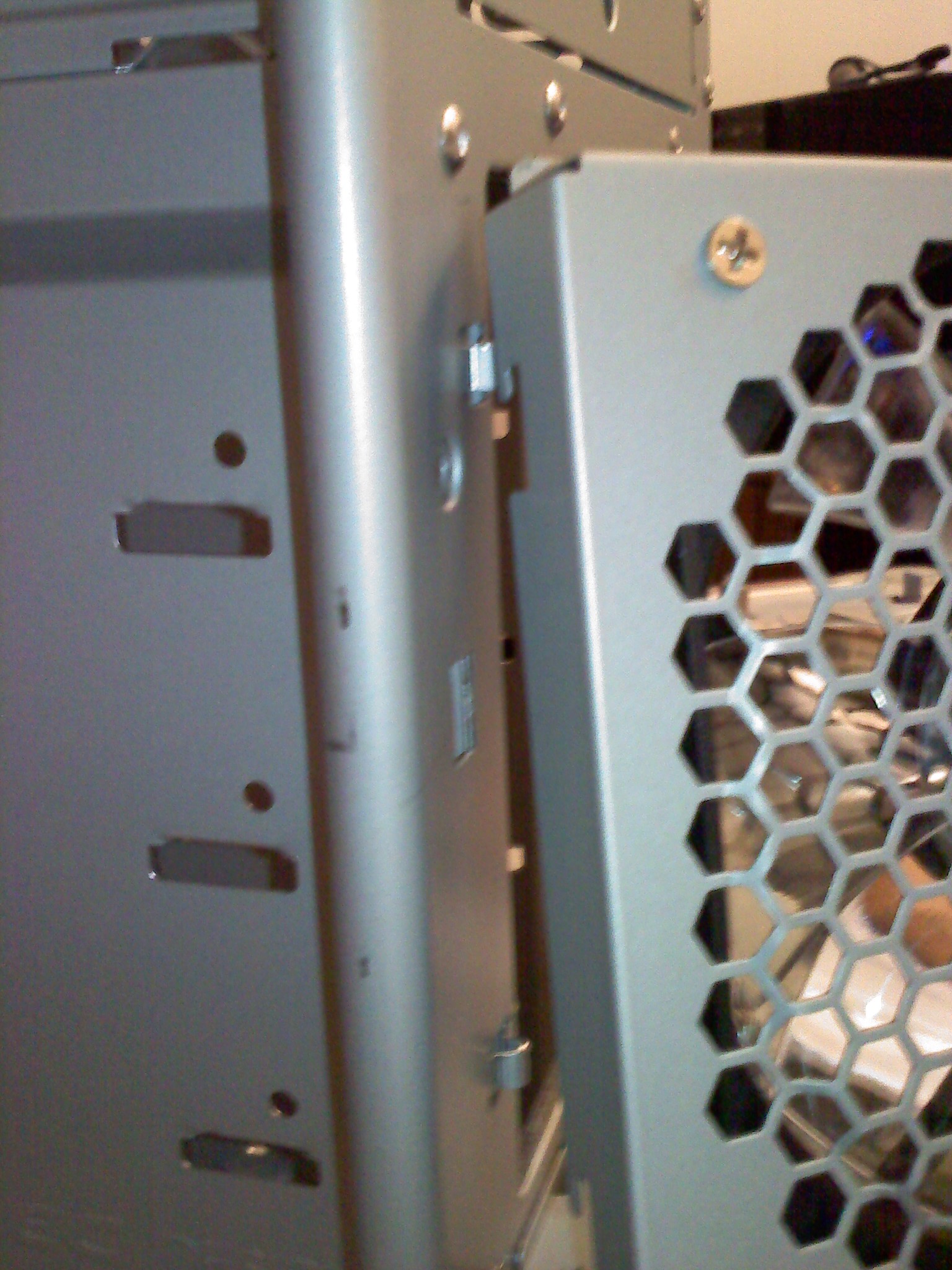
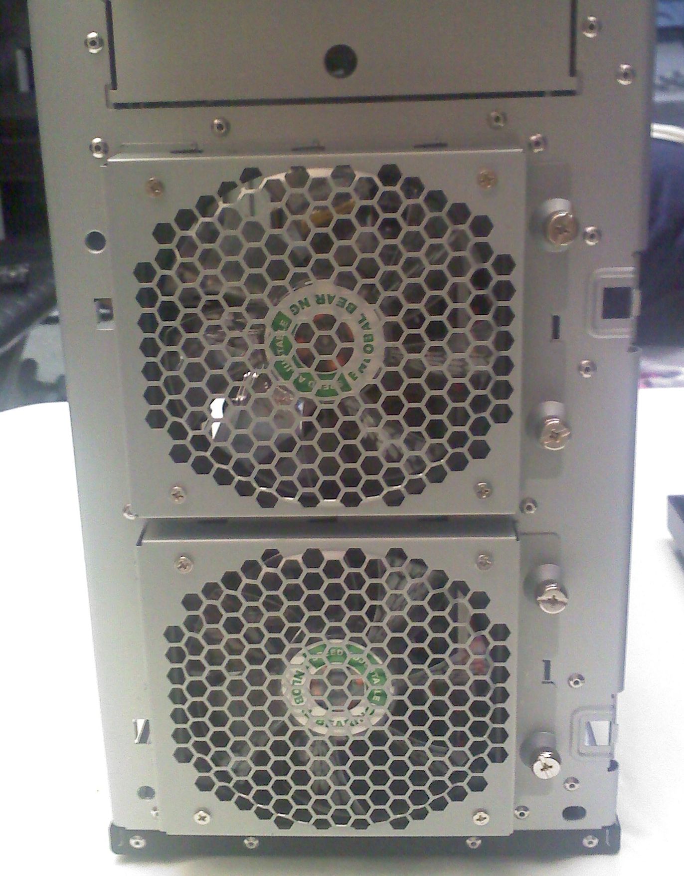
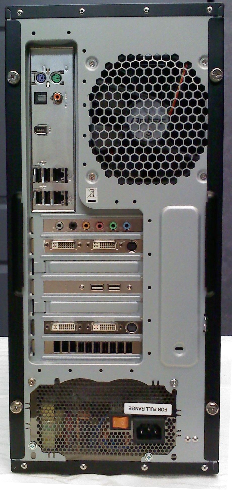
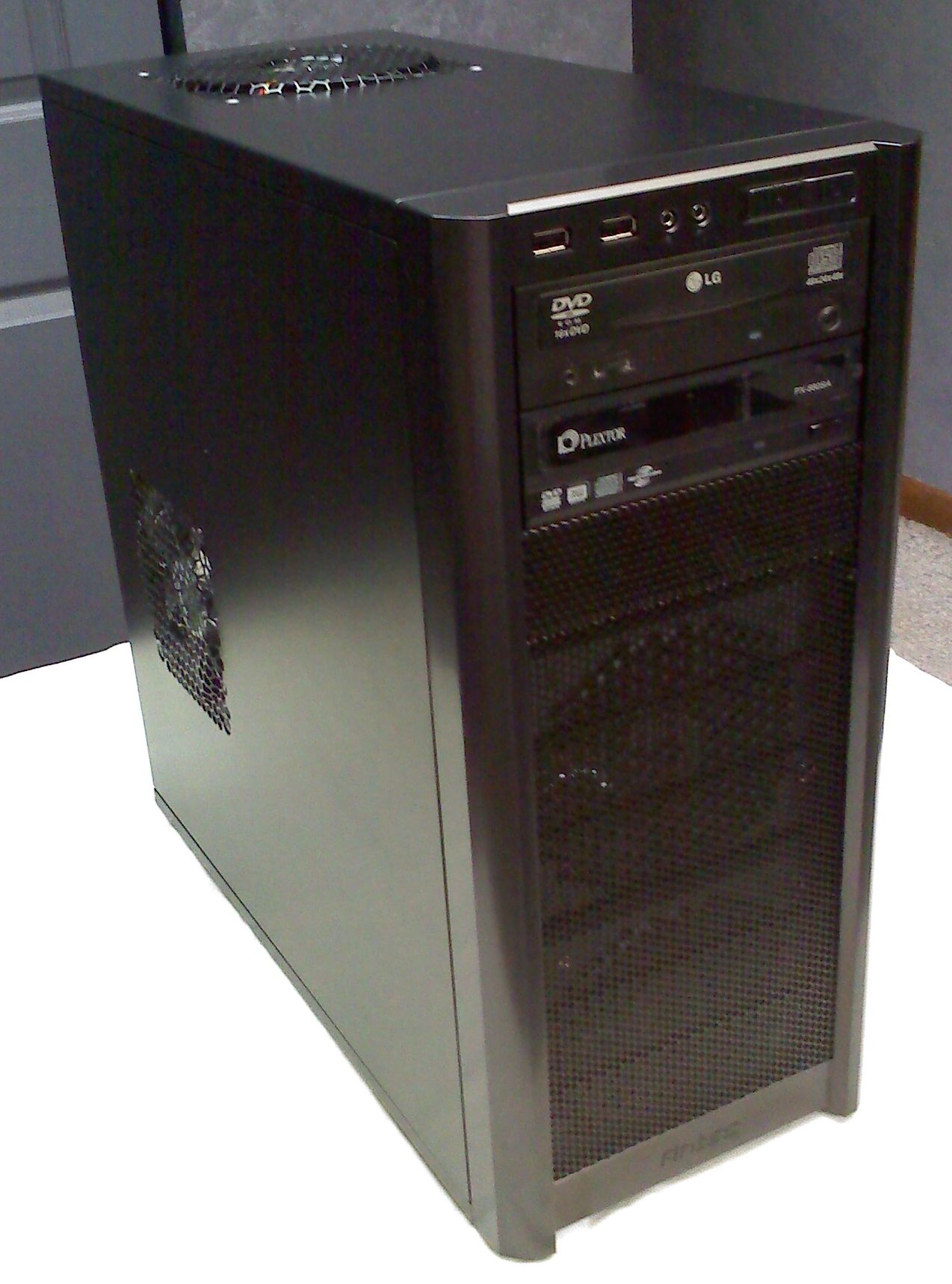
Once the left and right side panel are put in place and fastened down with their thumb screws, the build is done. I didn't take a picture of the side panel fan, but it's another Enermax 120mm fan and connects to a 4-pin Molex to three pin adapter at the bottom of the case near the PSU. (It's the black and red wire pair hanging out of the case in the picture of the full build above.) The first picture below shows the final build as it looks from the back. Note that this case has real removable and replaceable slot covers. A lot of cheap cases have knock out slot covers that can't be put back once broken out of a slot (except by using a slot cover from another case). The last picture is the finished view from the front and right of the machine. All and all it's a very sharp looking build.
The real payoff with this case is when we turn the power on. The new build is almost silent. Technically, so was the old build in the old case, but having no air movement tends to do that. The difference here is the internal case temperatures and those of the CPU have both dropped about 20°C to the mid 40s and mid 30s, respectively. That was the whole purpose of the transplant to the new case, and it's doing the job wonderfully. I think we'll keep it.
Arctic Cooling Accelero S1 Rev. 2 VGA Cooler
Arctic Cooling Accelero S1 Rev. 2 VGA CoolerAfter I upgraded from Windows XP to Vista Ultimate 64-bit, I happened to try out the latest Nvidia System Monitor tool. I set up the memory usage, CPU1 and CPU2 usage and the temps for CPU 1 & 2 and the GPU. And I looked at the GPU temperature and nearly excreted a rectangular, clay-based, building block. The idle temperature of my BFG 8800 GT OC was hovering at 70-75°C. I repeat: idle temperature.
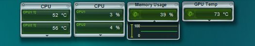
The temperatures & utilization with stock GPU cooling. 73°C @ idle!
That couldn't be right, could it? I tried a different tool and got the same result. Could this be the reason why some games seemed to cause the GPU fan to go to 100% and just stay there? I wasn't having any problems with the graphics card, but that temperature just can't be good. This card is factory overclocked, so I would expect it to run a bit warm, but not that warm. I tried running Fallout 3 for about 25 minutes and tabbed out to look at my GPU temp. 88°C! Shouldn't that cause the thing to melt?
Call to Action
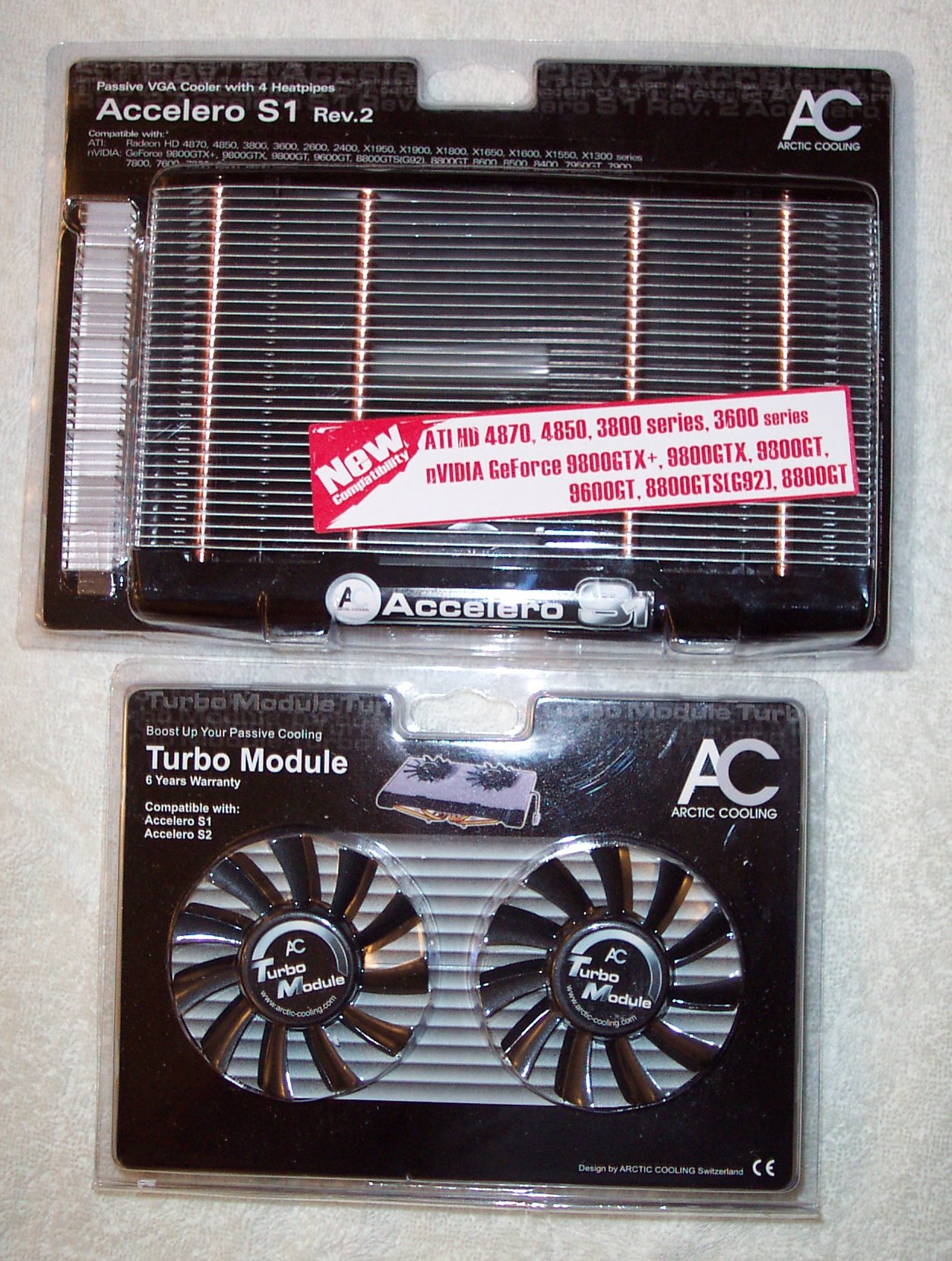
It was pretty obvious to me that I needed a VGA cooler. The question then was which one to get. There were a number to choose from, and they all seemed pretty competent. After a bit of research, I settled on the Arctic Cooling Accelero S1 Rev 2. It had a good price and previous buyers seemed pretty happy with the result, so I bought one from Newegg.com for about $25. This cooler is intended to be a silent cooler (with no fan), but my graphics card was running so hot, I opted for the add-on pair of fans for another $11.
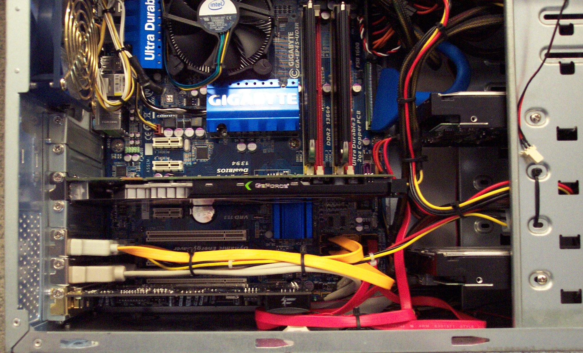
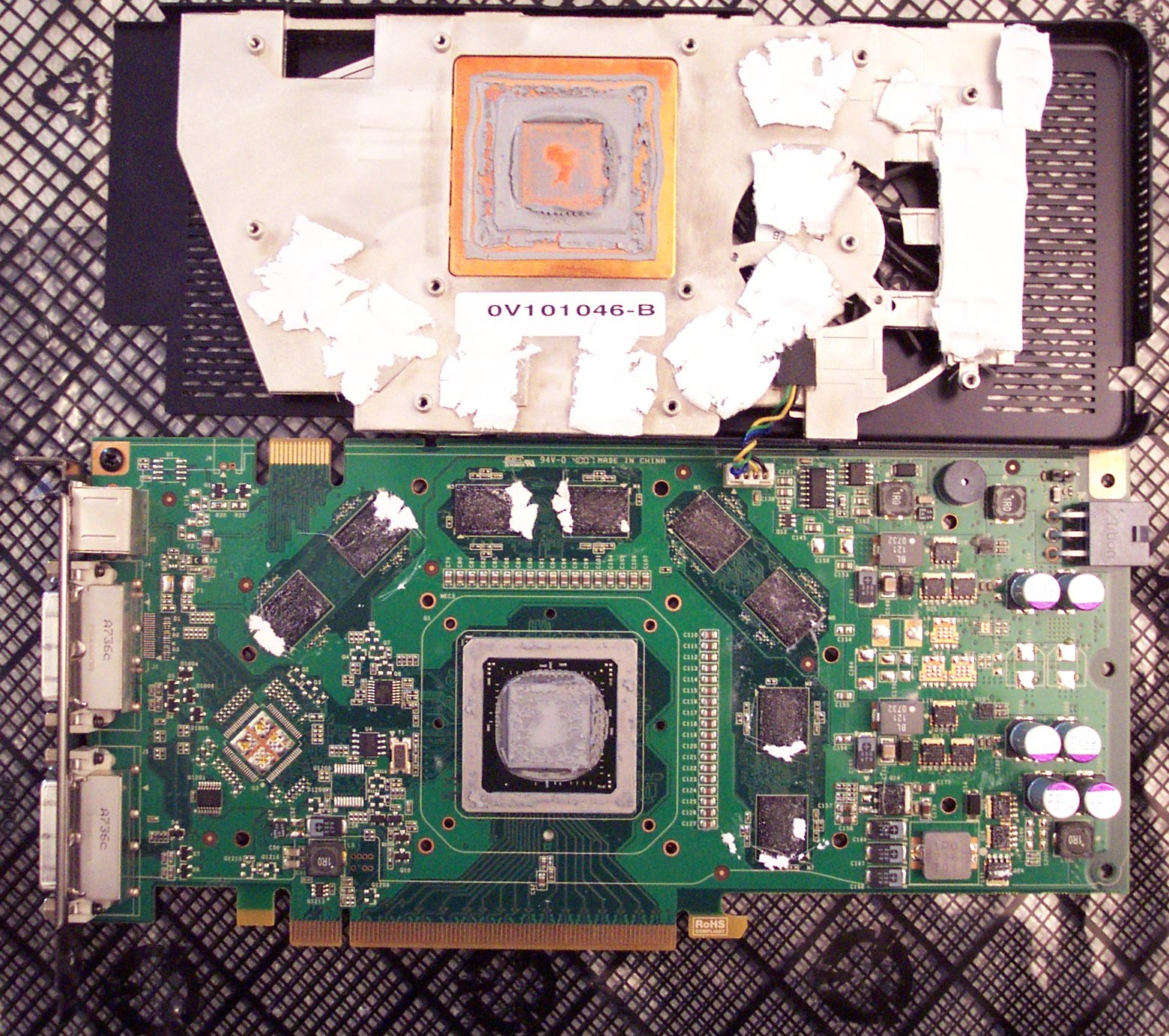
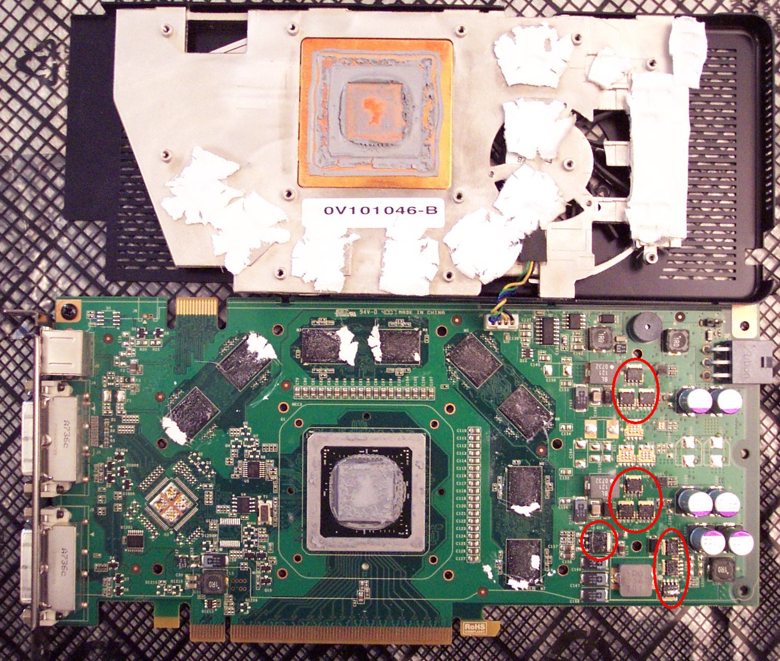
The first step of course is to remove the graphics card from the system. Looking at the card from the top here, it's obvious in hindsight that the little cooler on there just wasn't enough. Most of the video cards of the era have two-slot-wide coolers. After removing the card from the system to work on it, I finally got the meaning of the graphic of the bald-headed guy holding his head with both hands. “If this thing gets any hotter, it will explode!”

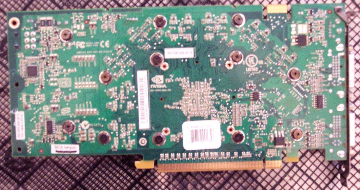
Now, I need to remove the original cooler. Just unscrew the .. 12 .. (Yep. Count 'em. Twelve.) screws that hold it in place on the backside of the card. I guess they didn't want the cooler to fall off. If they had just made it more effective rather than well fastened maybe I wouldn't have needed to do this. Even after the screws are all out, the cooler is held tightly to the card because of all the thermal paste and (sticky) thermal tape. It took a bit of prying and twisting the two halves slightly, but the two did come apart. Disconnecting the wire from the cooler's fan is the last part of removing the stock cooler.
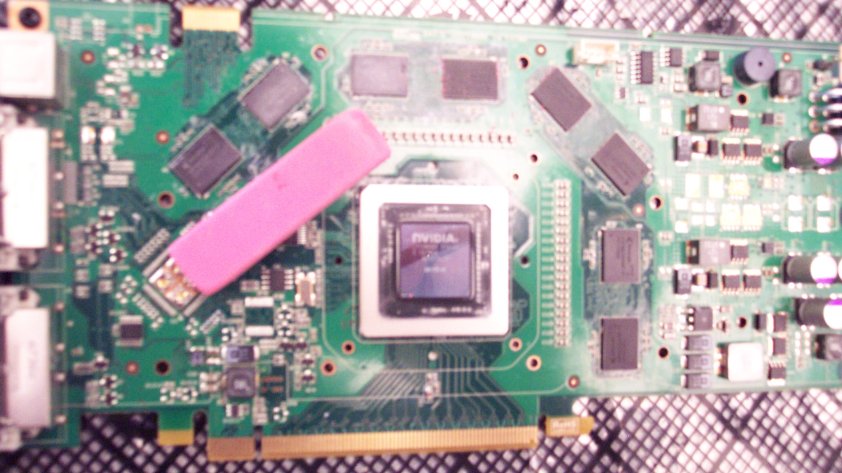
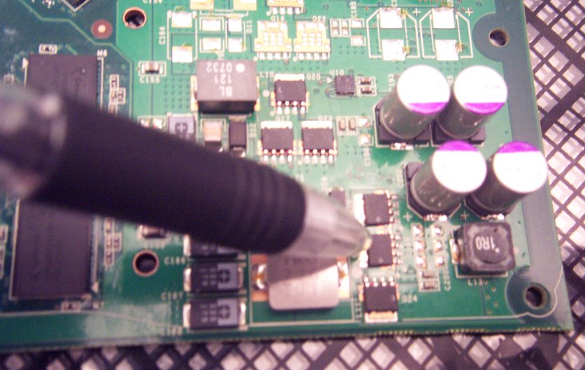
The next step is to clean off all the thermal paste from the GPU, memory and voltage regulator chips. This is done using a soft wipe and isopropyl alcohol with a purity of at least 90% (It's available in most drug stores, but often not found in most groceries.) Handi Wipes® are very good for this, but decent paper towels will do. Put the alcohol on the cloth - not on the card directly. Clean with a circular motion until as much paste can be removed is gone. An Xacto knife with a sharp point can (gently) be used to remove the paste from the corners. There may still be some residue left on the memory chips left behind by the adhesive of the thermal tape. This is where the trusty Pink Pearl eraser comes in. Gently rub the surface of the chips (the memory and voltage regulators in my case) until they loose any slickness. (In the second image below, the three memory chips to the right of the GPU have been “erased” of remaining adhesive.) Clean the chips one last time with alcohol and we're good to go.
The Arctic Cooling Accelero S1 Rev 2 also includes a set of self-adhesive heat sinks for the memory and the voltage regulators. The memory we cleaned above, but we also need to clean the voltage regulators. How to we tell which chips are the voltage regulators? In my case, it was pretty simple. Looking at the cooler that I removed, it is easy to see which chips the manufacturer thought were important enough to but thermal tape on. Using that as a guide, the first image below shows the chips to receive new heatsinks outlined in red. Using an Xacto knife, we peel the backing from one of the voltage regulator heatsinks. We do the same for the memory heatsinks as well and press each of them into place. When we're done, we have a card full of heatsinks like the one in the last picture below.

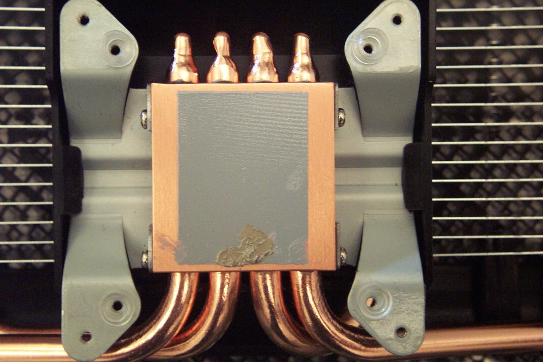
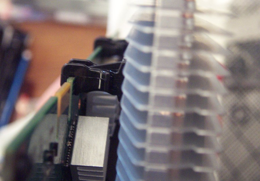
Now, it's time to bolt on the new GPU heatsink. (Picture 1) Both the card and the Accelero S1 have two sets of holes for screwing the GPU heatsink to the motherboard. We'll use the inner set. Picture 2) The first task is to remove the double stick tape backing and affix the four rubber/plastic spacers to the bottom of the heatsink. ((You do not see where I had to patch the thermal paste on the heatsink after scratching it during a test fit.) (Picture 3) We then fasten the four screws with an even number of turns of the screwdriver on each screw to maintain an even, snug fit. (Picture 4) The final step is to thread two plastic clips through the fins on the Accelero S1 so that they line up with and clip to the top of the graphics card. These provide extra support to the cooler.

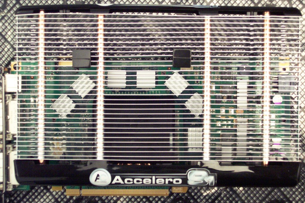
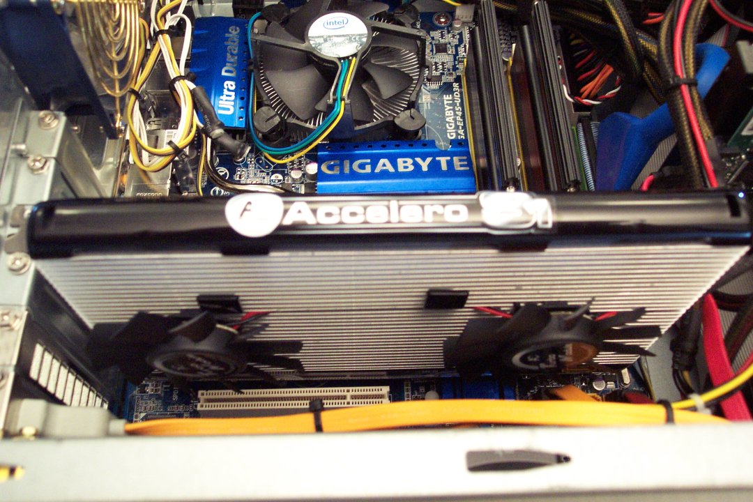
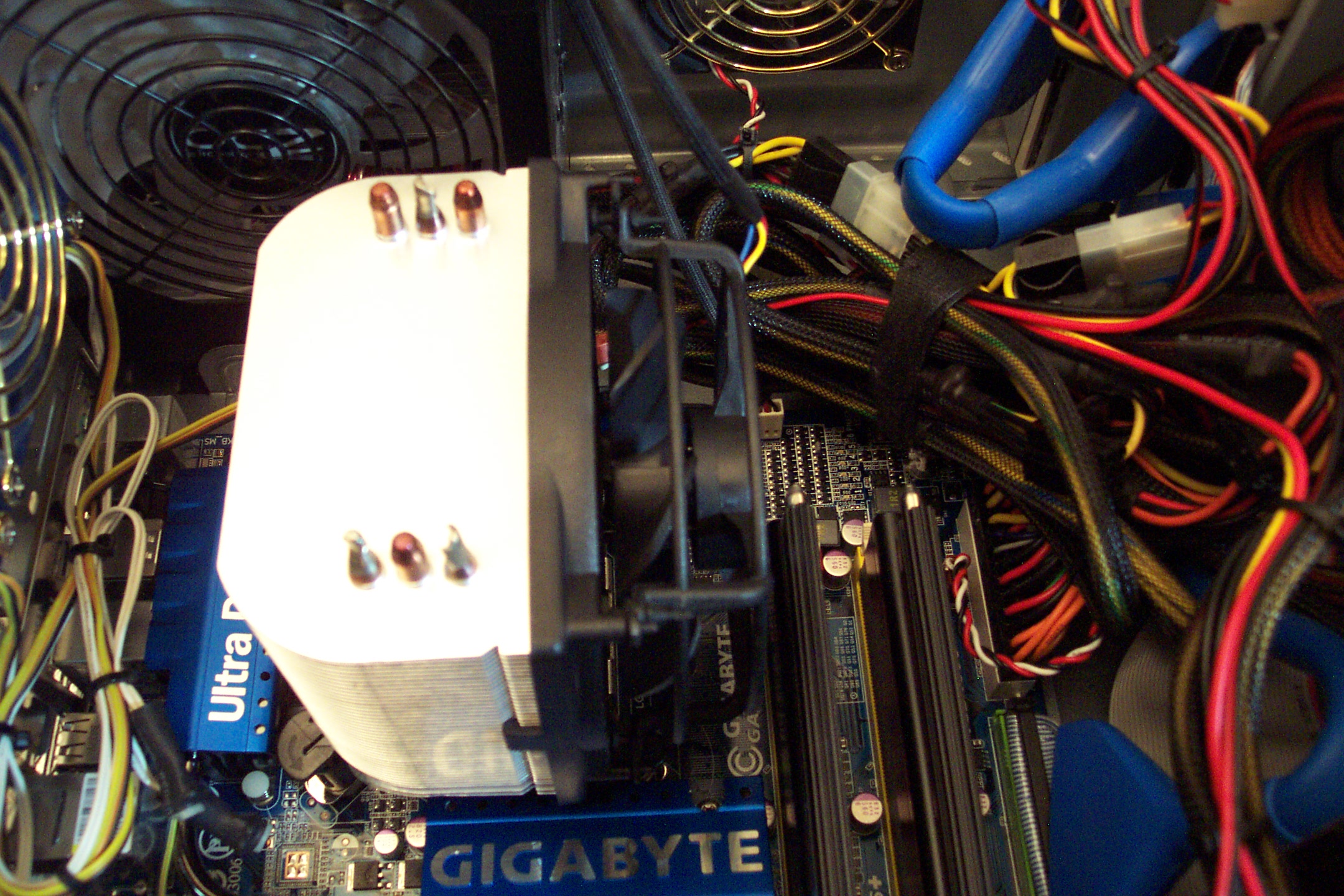
(Picture 1) All that's left is to clip on the dual fans and reinstall the new & improved graphics card. (Picture 2) The top view shows how much room the Accelero S1 takes up. It's two slots as a minimum and with the optional fans, it's three slots. In my case, it's not a big issue as I only have one other (PCI) card anyway, which is for my Creative Labs X-Fi Fatal1ty audio card.
So, the $10,000 question - well really the $40 question - “Was it worth it?” I think the numbers speak for themselves. The first temperature graph below is the idle temperature just a short while after booting up the machine. I let the temperature settle out, and this is where it settled. It's a full 30°C cooler than before. That's already a good sign. Next, I played Fallout 3 for a few hours, tabbed out and snapped another screen capture. It went up 5°C in three hours of game play. That's it. 5°. Just for good measure, I let it run all night to see if it stayed stable. Sure enough, the idle temperature was 42°C. I'm sure I didn't even need the optional fans. This could have been a completely quiet VGA cooler. But I paid for them, so in they go. I can't believe I waited a year to get this cooler. My suggestion to you is don't wait.
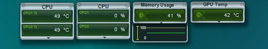
The temperatures just after installing the Accelero S1. 42°C @ idle! Amazing reduction.
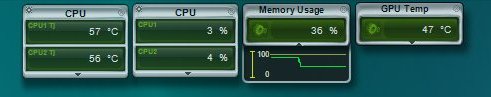
The temperatures after three hours of Fallout 3. At 47°C, it's not even sweating.
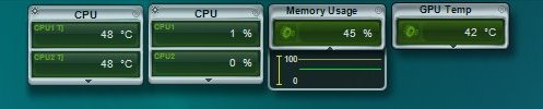
The temperatures after letting the system run all night. Again 42°C @ idle!
Arctic Cooling Freezer 7 Pro CPU Cooler
Arctic Cooling Freezer 7 Pro CPU CoolerWith my success and happiness with the Arctic Cooling Accelero S1 Rev 2 VGA cooler, I decided that I should look into a CPU cooler as well. While my CPU temperatures at 51°C during idle weren't too bad, they were still higher than I would like during gaming at 74-76°C. That's a rise of about 23°C under load. My method for testing was to run the first CPU test of Futuremark's 3DMark06, stop it and take a screenshot as quick as possible. Not completely accurate, but close enough.
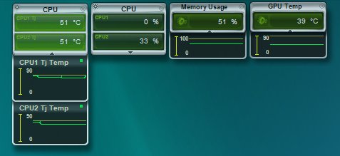
The CPU (and other) temperatures & utilization with stock cooling @ idle.
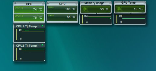
The CPU and other temperatures & utilization with stock cooling while testing.
The Solution
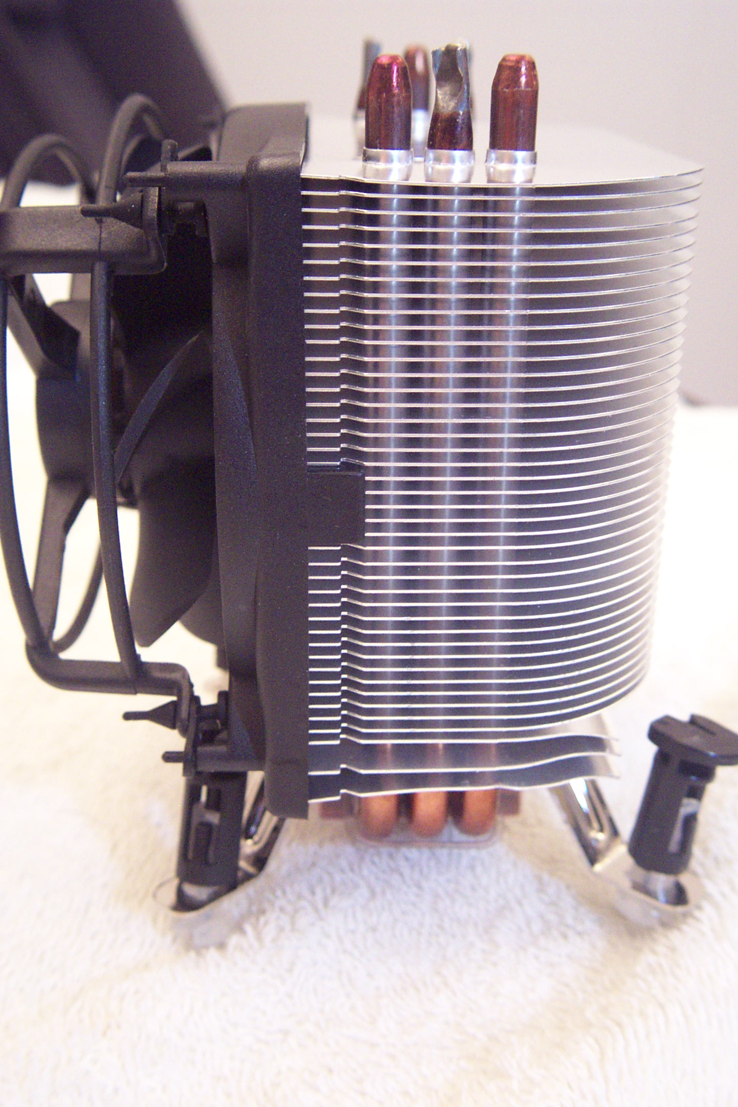
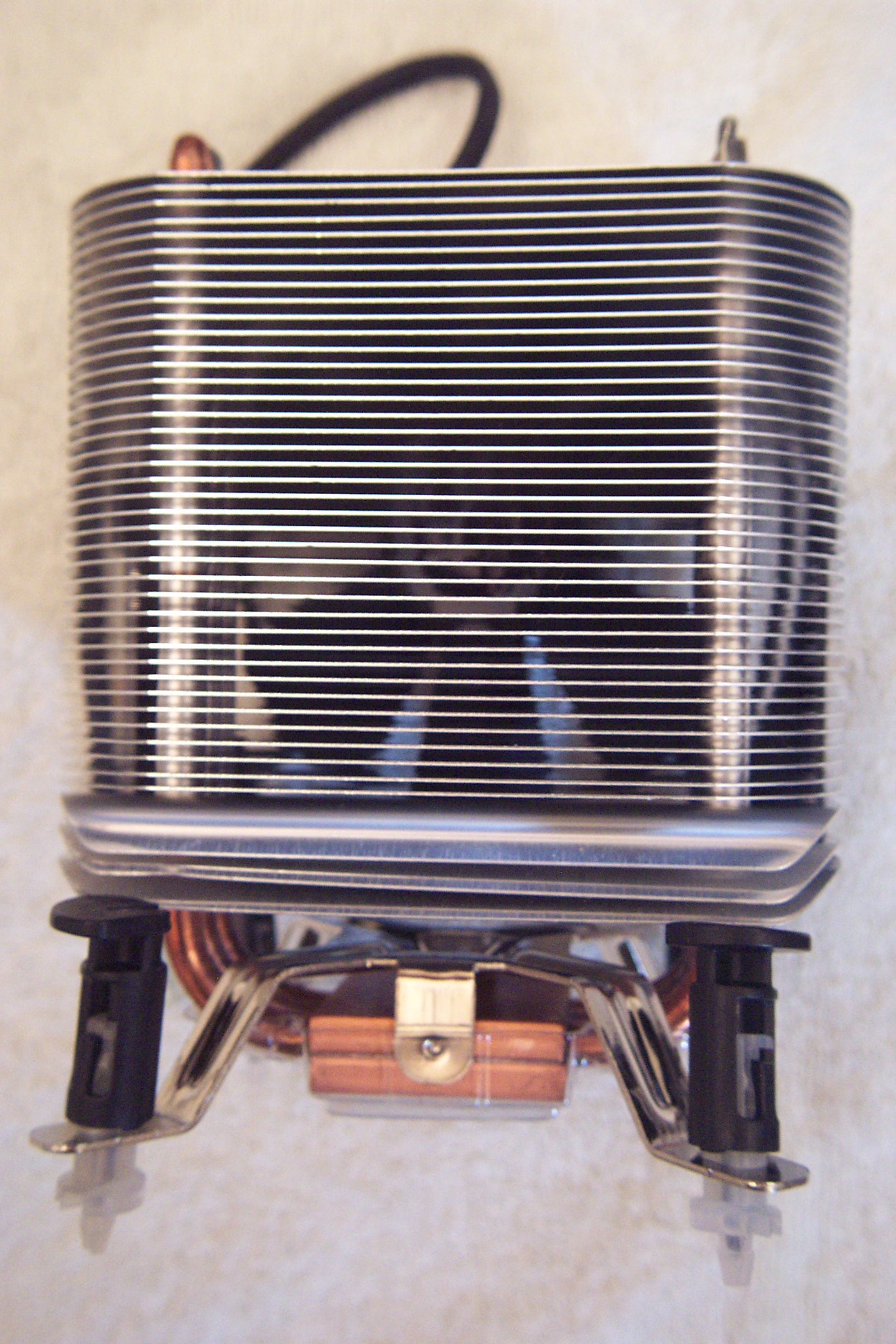
Since I had such a dramatic result with the Arctic Cooling VGA cooler, I thought I would try their Freezer 7 Pro CPU cooler. The first thing that's noticeable about the Freezer 7 Pro is that it is a monster. I didn't have any problems, but I could bet there might be with some motherboards where the memory is very close to the CPU. That said, I have the OCZ Reaper HPC 4GB DDR2 1066 (PC2 8500) memory kit that has the heat pipes above the memory. I didn't have an issue, but it was close. First, a gratuitous box shot of the product, which shows its basic design.

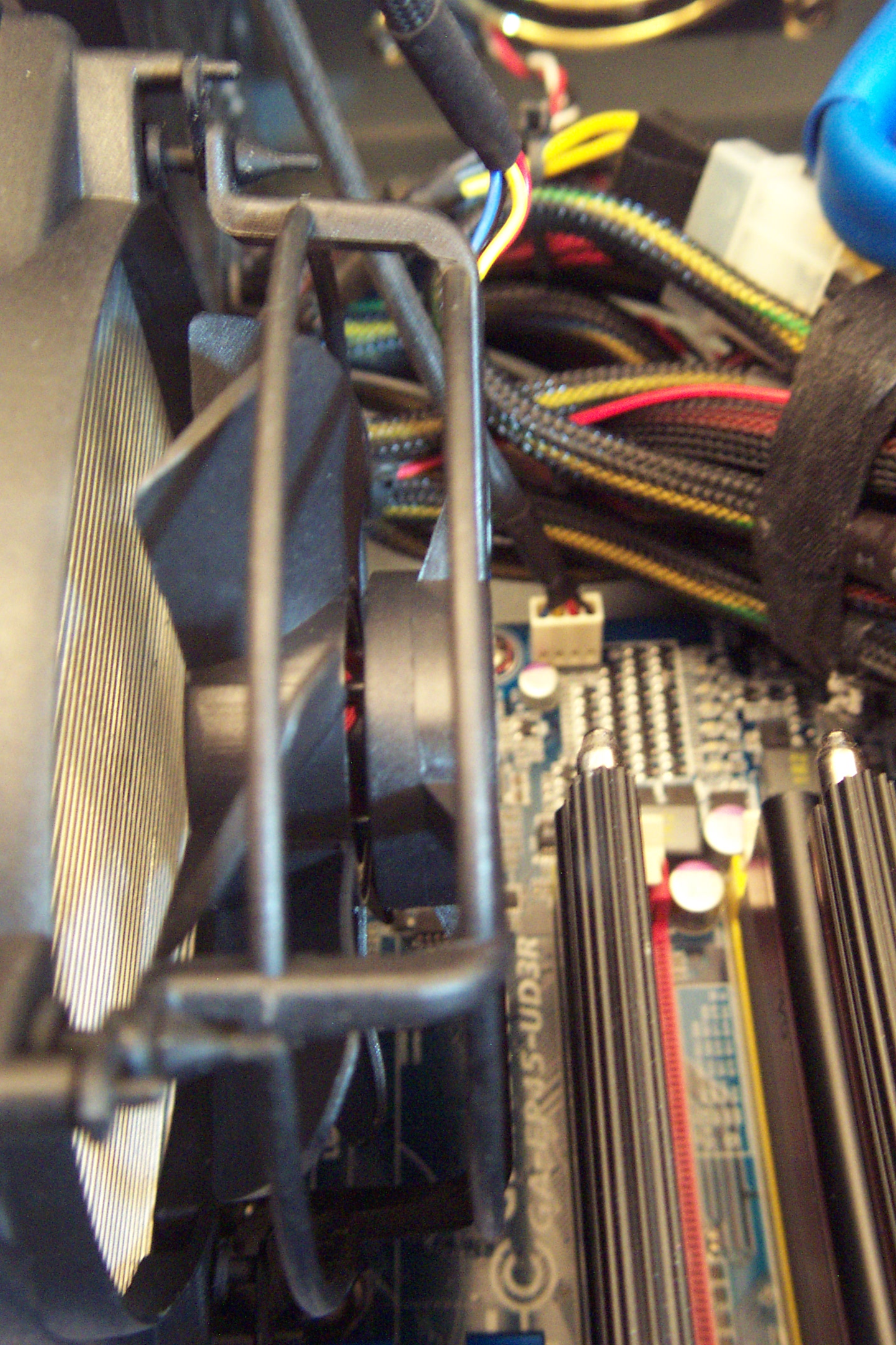
As you can see from the pictures, this is a large heatsink and fan combo with three heat pipes through the fins. It has a good-sized 92mm fan that pushes air toward the back of the case. In my case, that air goes right into a 120mm exhaust fan. Because it's 92mm, it can run slower and still move a good volume of air. Slower generally means quieter. (You could also orient the cooler to put the air toward the top of the case as well, for those cases where the power supply is on the bottom and there is clear air flow out the top.) The lowest three fins are curved downward on the front. Their purpose is to blow air down on the voltage regulator/converters .. assuming that's where yours are located.

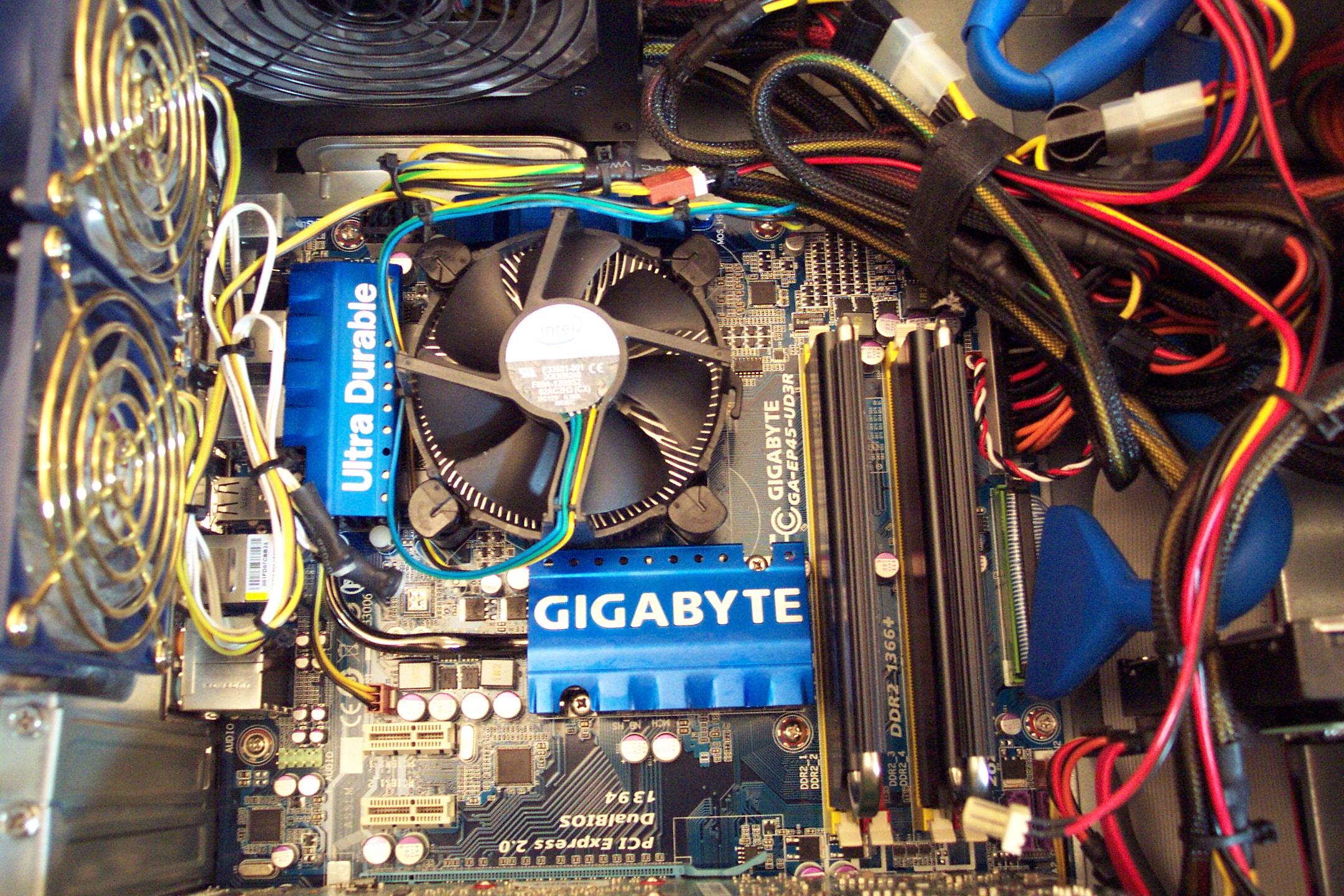
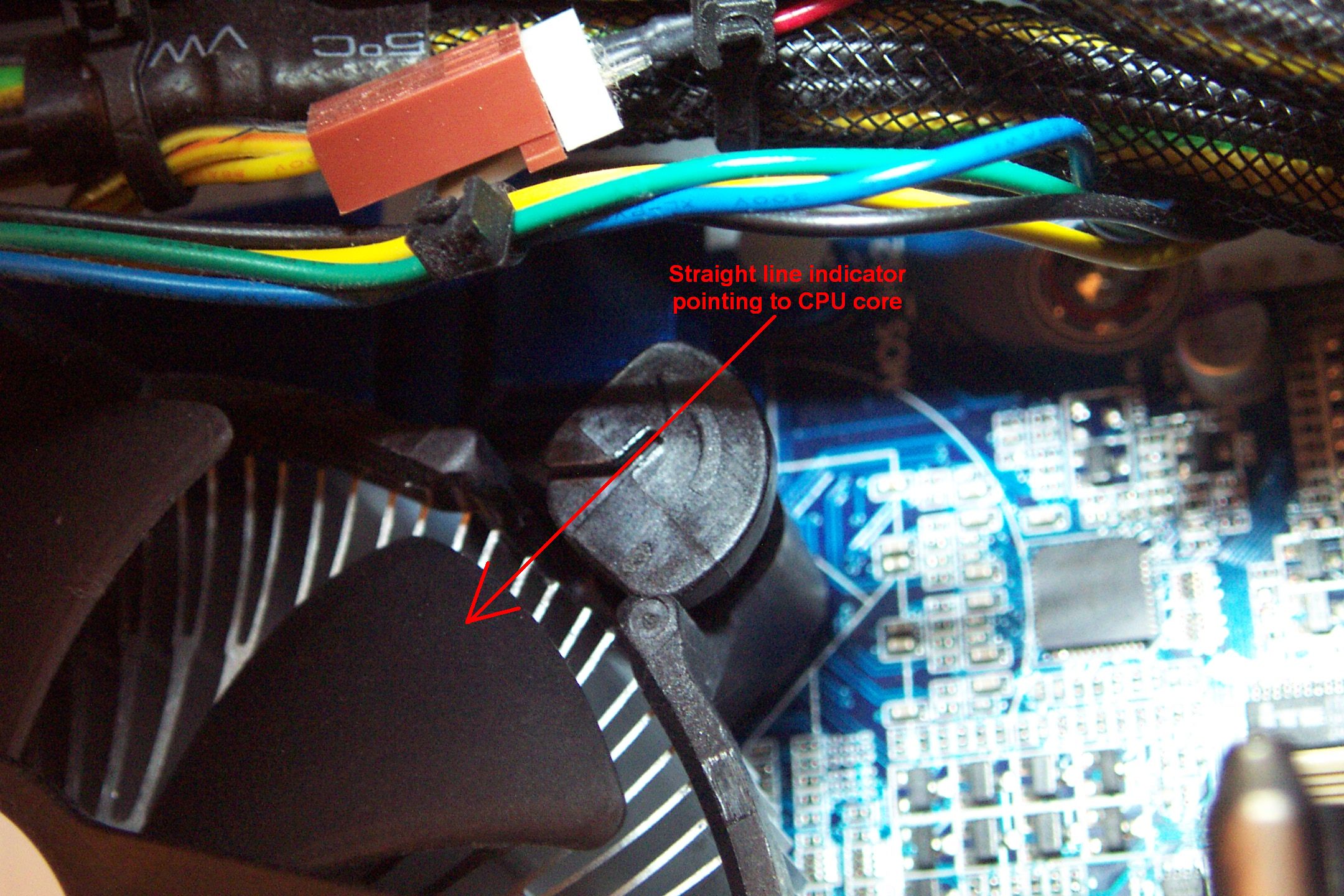
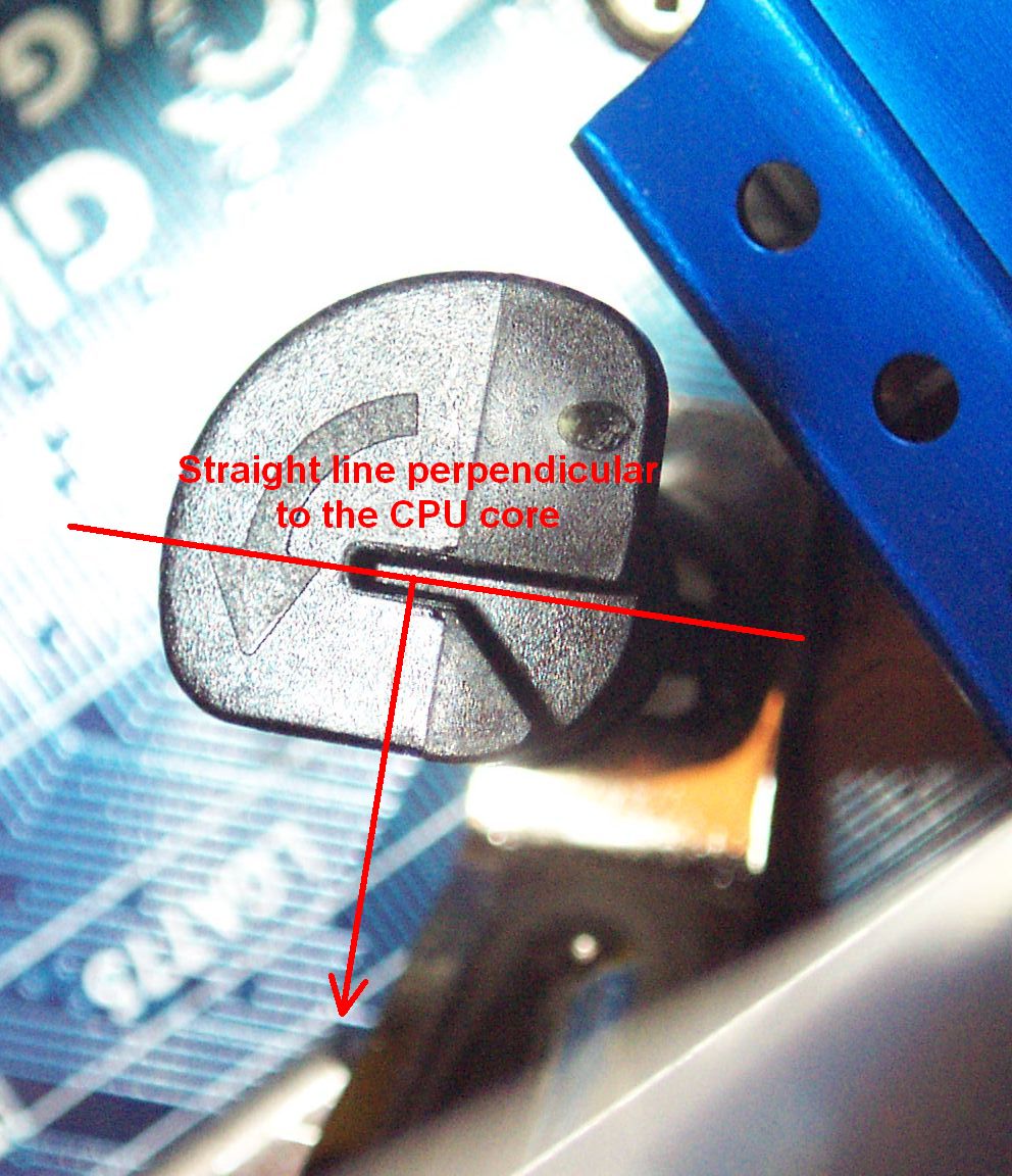
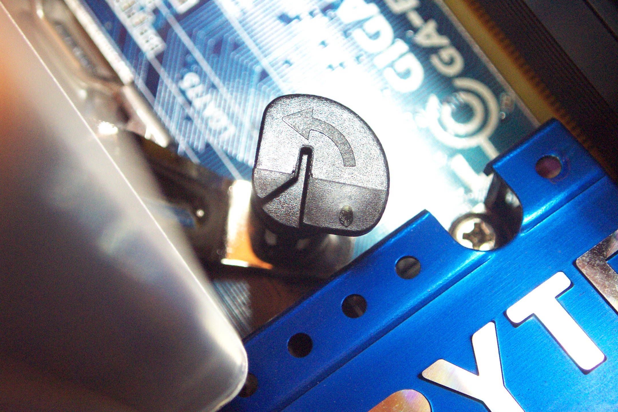
The first step is to remove the original stock cooler. Mine is the cooler that comes with the retail version of the Intel Core 2 Duo E8500. First, we disconnect the wire that connects the fan to the motherboard. This heatsink fastens to the motherboard like most LGA775 heatsinks. That is with four plastic posts positioned equilaterally around the base. Note that when the posts are locked, the "straight line" indication on the top points toward the CPU core as in the first close-up picture. Use a large flat-blade screwdriver inserted into the slot and unlock the post by turning it 90° in the direction of the arrow as in the second close-up. (This is actually a picture of the post on the new heatsink before it was locked in place, but the position of the top of the post is the same.) The "straight line" should be perpendicular to a line going to the CPU core. It can be pulled straight up out of the motherboard. Repeat for all four posts.
Rant warning: After years of both Intel and AMD coming up with simpler, more fool-proof designs for connecting heatsinks to motherboards, Intel took a decade-wide step backwards with the LGA775 socket. We want a heatsink that can be attached to the motherboard with a simple lever or something similar to lock it in place. Intel, you had it right with the Socket 478 design. AMD is still getting it right with their AM2/AM2+/AM3 motherboard sockets. Please, please, please beg, borrow or steal a better design. It's extremely hard and sometimes nearly impossible to push the post down and turn it at the same time. It's very hard when the motherboard is attached to a case to see if the post is through the motherboard and locked correctly. In this day and age shouldn't have to flip the motherboard over to look. I push one post in and the one on the opposite side pops out. Then I have to resort to pushing both posts down as hard as possible while locking one into place. That the LGA1366 socket still has the same crappy design as the LGA775 saddens me. I'm quite surprised that there hasn't been a cottage industry of just selling better posts for these heatsinks.
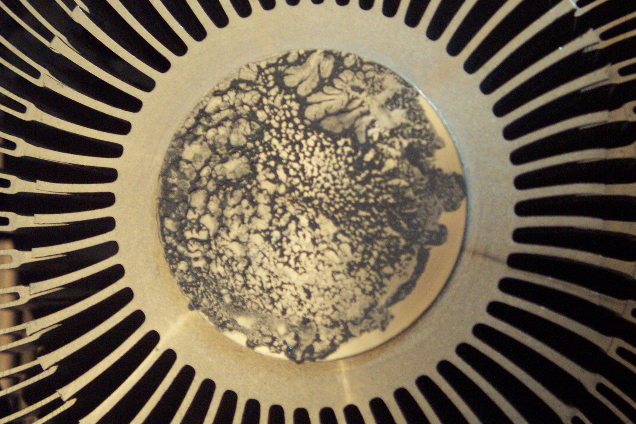
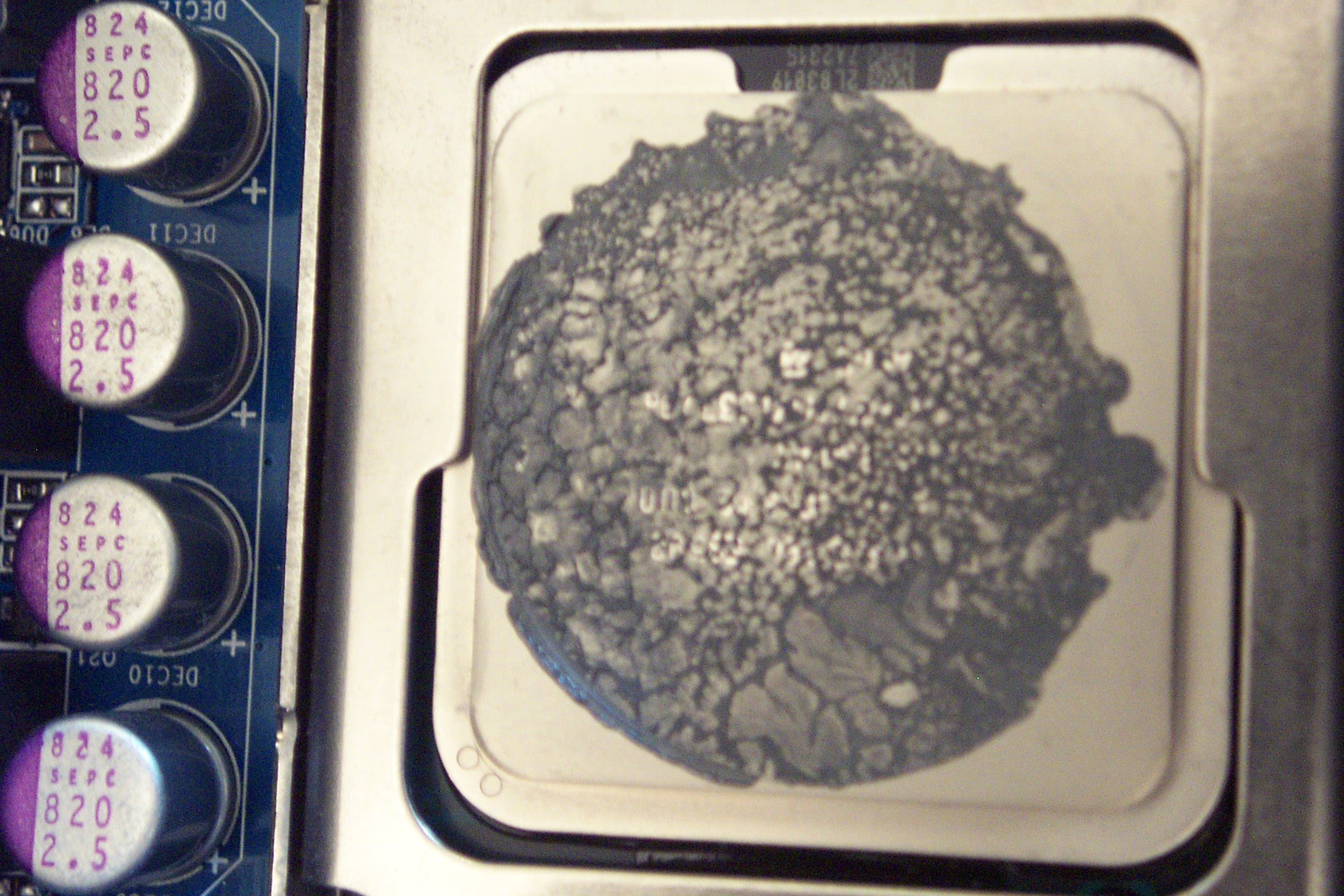
I was really disappointed at what I found upon removing the heatsink, flipping it over, and looking at the surface that contacts the CPU. As you can tell from the picture, the thermal transfer compound - in this case, the Intel supplied thermal tape - has pock marks and one edge isn't even covered. It appears that the thermal compound has boiled away to some extent or at least dried out. Looking at the top of the CPU, we see the same thing. The edge that isn't covered is probably due to the heatsink not contacting the surface of the CPU package squarely, and that, I blame squarely on the crappy heatsink attachment design.
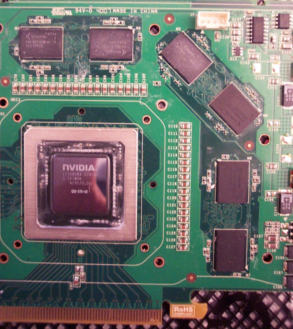
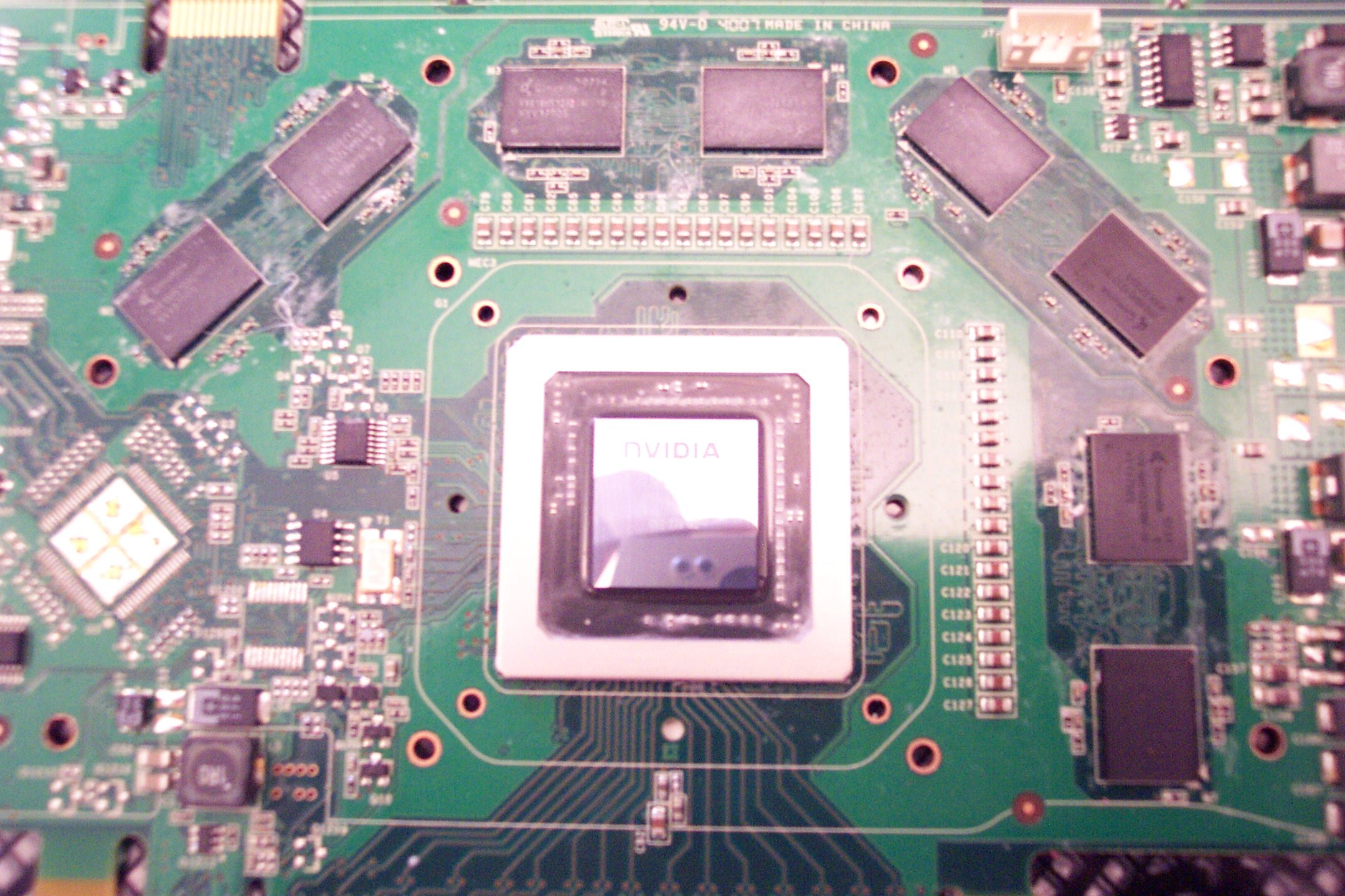
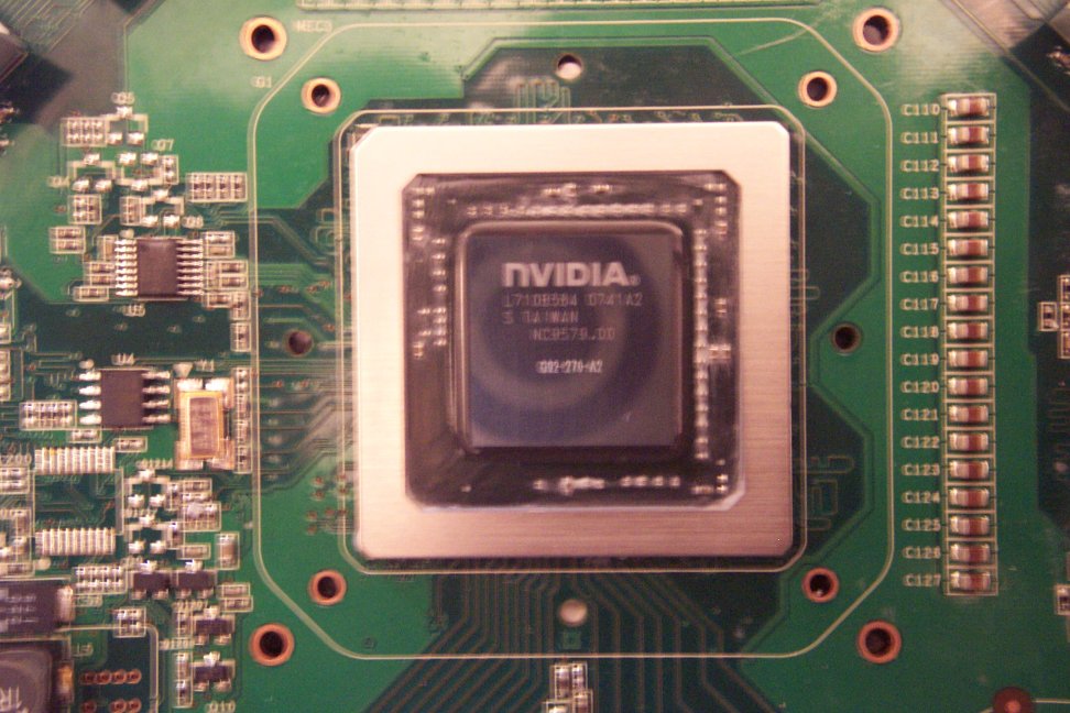
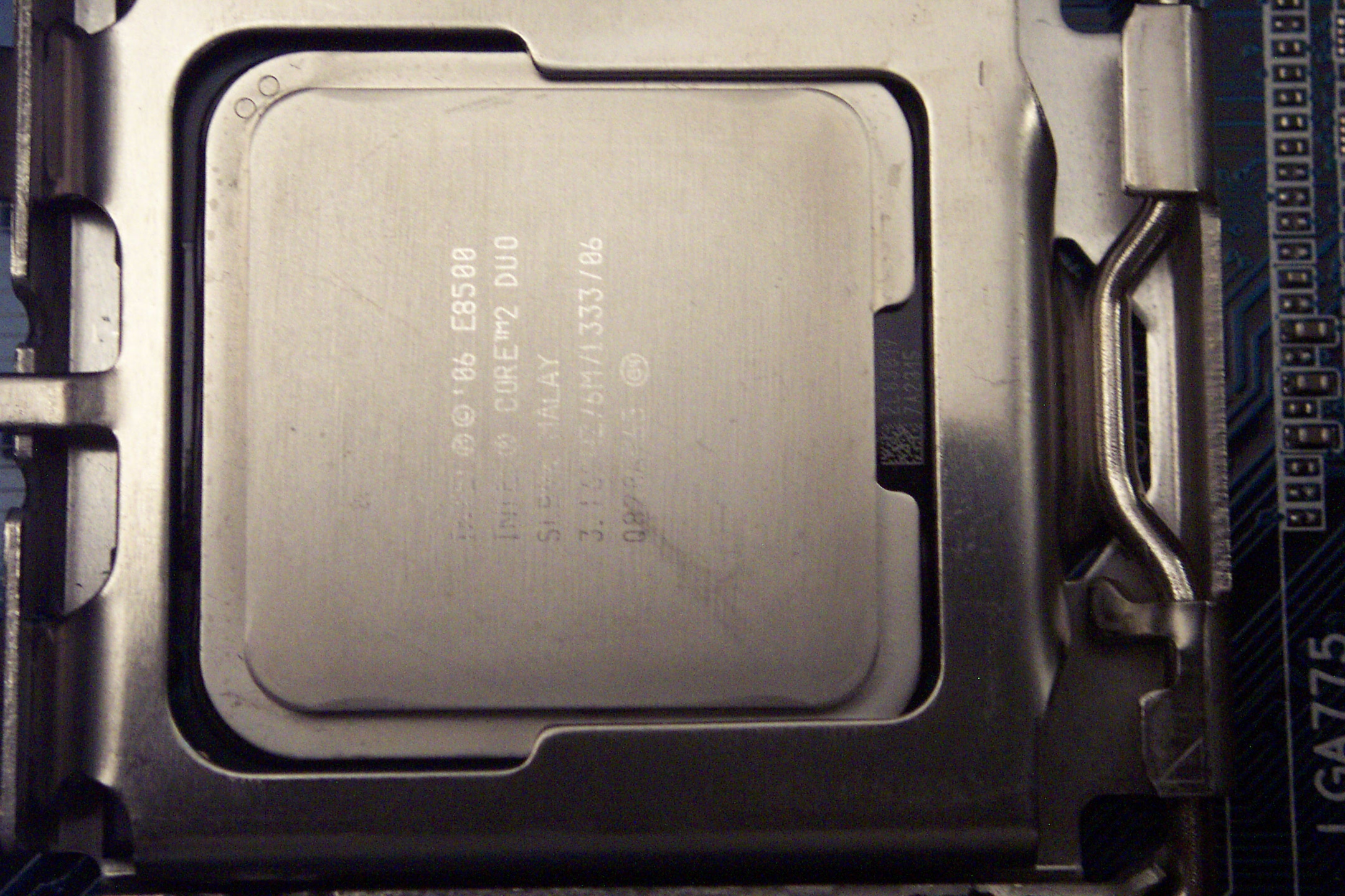
The next step is to clean off all the thermal paste from the top of the CPU. This is done using a soft wipe and isopropyl alcohol with a purity of at least 90% (It's available in most drug stores, but often not found in most groceries.) Handi Wipes® are very good for this, but decent paper towels will do. Put the alcohol on the cloth - not on the CPU directly. Clean with a circular motion until as much paste can be removed is gone. An Xacto knife with a sharp point can (gently) be used to remove any remaining paste. When it's clean, it should be easy to read the specs on the CPU.
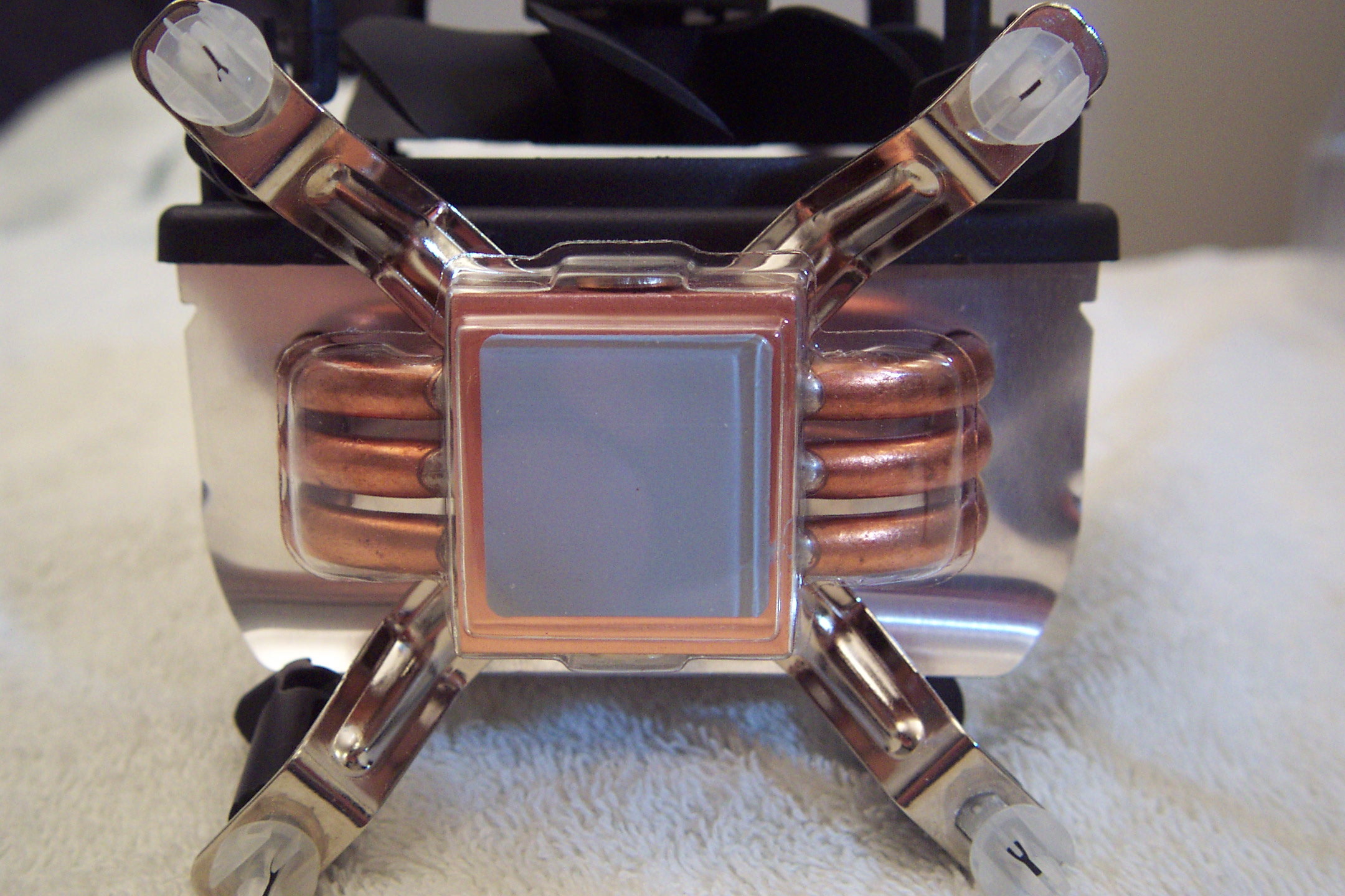
The next step is to put new thermal compound on top of the CPU. There are many good choices out there, but I like Arctic Silver 5. There are a couple good Youtube videos on applying Arctic Silver 5 and a set of PDFs from Arctic Silver as well. I won't go into detail here as this isn't a tutorial on replacing a heatsink. The freshman mistake most people make is putting (way, way) too much compound on the CPU. As the instructions say, a glob the size of a grain of rice or a grain and a half is sufficient for most CPUs. I myself like spreading the compound with a straight razor blade, but the way recommended by Arctic Silver is to just put the glob in the center - as a line with the proper orientation for dual and quad core CPUs - and to press and twist the heatsink down on the CPU as flatly as possible. The twisting will spread the compound around. (I believe it will spread further and evenly once the CPU heats up as well.)
Now, it's time to fasten the new CPU heatsink to the motherboard. (Picture 1) Position the heatsink over the motherboard and align the four posts with the four holes in the motherboard. The Freezer 7 Pro is installed with the fan off the unit, so be sure to orient the heatsink so the airflow will be in the direction desired. In my case, the airflow is toward the back of the case. This is what most people will want, however, if you have a case with the power supply on the bottom and a fan at the top of the case, you may want to orient the heatsink to push the air to the top of the case. (This may defeat the purpose of the bottom curved fins in cooling off the voltage converters, however.) (Picture 2) Initially all four posts should be oriented with the "straight line" perpendicular to a line going to the CPU core. (Picture 3) Use a large flat-blade screwdriver inserted into the slot and while pressing down - harder than you would like in order to extend the post though to the bottom of the motherboard - turn the post 90° clockwise opposite of the direction of the curved arrow on the post. I've seen a lot of instructions have this backwards. The arrows are there to show how to remove the heatsink, not install it. You may need a pair of screw drivers, one on the post you are locking and one on the post opposite of that one (or use your thumb on the opposite post), to keep from popping out or moving the heatsink while fastening down the post. Repeat for all four posts. If you happen to have the motherboard outside the case (as when building a new PC), look under the board to see if the pins on the post are completely through the motherboard.
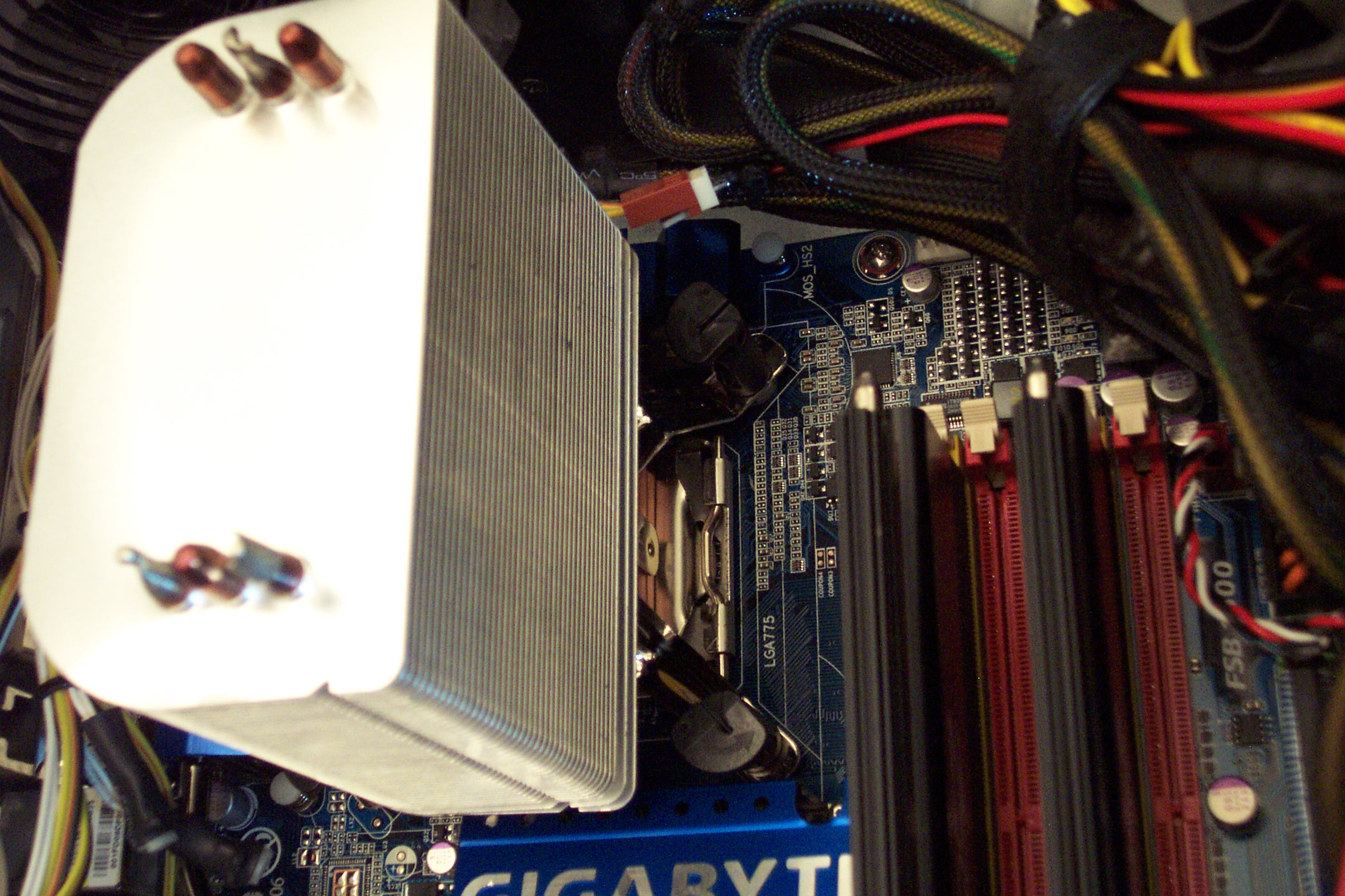

Now, it's time to attach the fan to the heatsink. The Freezer 7 Pro makes this easy in that it's just a couple clips that hold the fan mounting to the heatsink. The fan itself is attached to the mount with rubber fasteners to dampen down the noise from fan vibration. All that's left is connect the 4-pin fan power connector to the motherboard. Now, it's time to see if the effort pays off.
It's time to take the same temperature settings and see what we've gained. The differences aren't as dramatic as with the Arctic Cooling Accelero S1 Rev 2 VGA cooler, but then the situation wasn't as bad to begin with either. A 10°C reduction in idle temperatures and a 12-15°C reduction in temperatures under load is very respectable. I've since overclocked my CPU from 3.16GHz to 3.6GHz with no appreciable difference in either the idle or load temperatures. The Arctic Cooling Freezer 7 Pro CPU Cooler definitely gets a thumbs up from me.
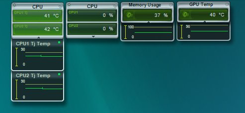
The temperatures just after installing the Freezer 7 Pro. 41 & 42°C @ idle. A full 10°C reduction in idle temperatures.
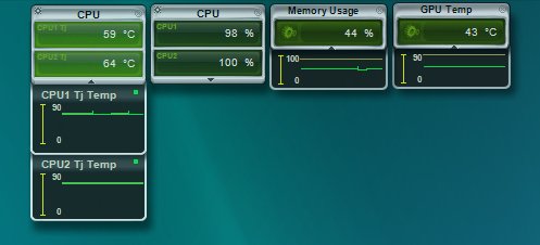
The temperatures under load of the 3DMark06 CPU test 1. 59 & 64°C. A 15°C & 12°C reduction in temperatures under load.